Answered step by step
Verified Expert Solution
Question
1 Approved Answer
1 . Subnet the 1 9 2 . 1 6 8 . 0 . 0 / 2 3 network into 3 smaller networks that meet
Subnet the network into smaller networks that meet the following criteria. Use VLSM to waste as few IPs as possible.
a VLAN Blue:
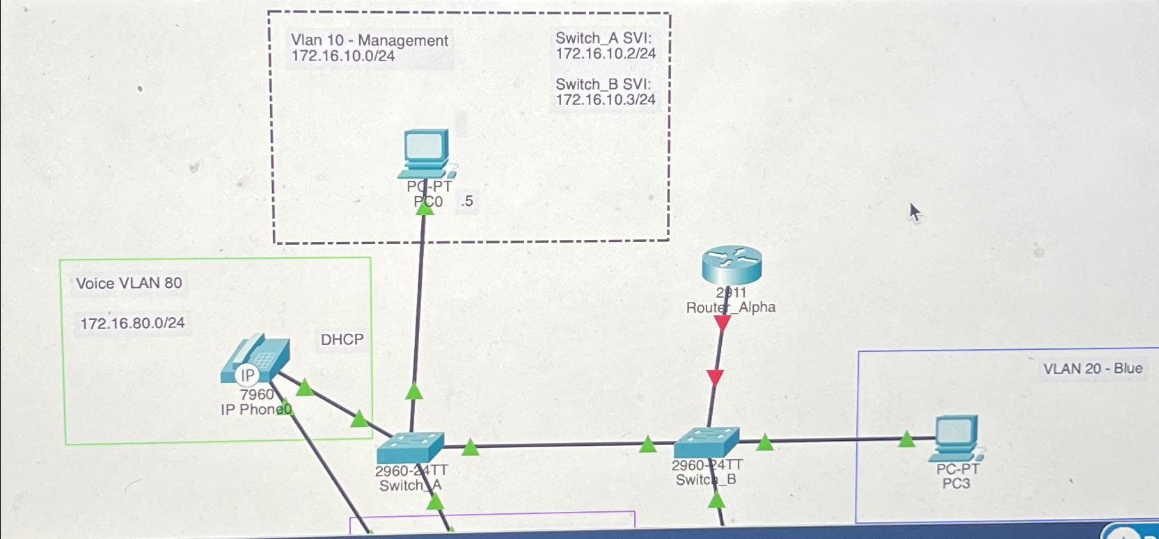
hosts Gateway is assigned the first available IP PC is assigned the second available IP b VLAN Red: hosts Gateway is assigned the first available IP PC is assigned the second available IP c VLAN Purple: hosts Gateway is assigned the first available IP PC is assigned the second available IP PC is assigned the last available IP SwitchA Configuration Instructions Apply the following configuration to SwitchA: SwitchA config# no ip domainlookup SwitchA config# hostname SwitchA SwitchA config# service passwordencryption SwitchA config# banner motd #No unauthorized access!# Configure the following VLANS with their respective names.VLAN IDVLAN NAMEManagementPurpleVoiceMiscNative Create an SVI for VLAN using the IPv address show in the topology Set interface fa as an access port that is assigned to VLAN Management using the following commands:SwitchA config# interface faSwitchAconfigif# switchport mode accessSwitchAconfigif# switchport access vlan Set all interfaces connected to hosts as access ports and assign them to their respective VLANs in accordance with the topology. Do not forget the voice VLAN on interface fa Set interface fa as port that will dynamically configure itself as a trunk DTP using the following commands:SwitchA config# interface faSwitchAconfigif# switchport mode dynamic auto Configure interface fa to use VLAN as the native VLAN using the following command:SwitchA config# interface faSwitchAconfigif# switchport trunk native vlan Configure interface fa to allow VLANs and across the trunk using the following commands:SwitchA config# interface faSwitchAconfigif# switchport trunk allowed vlan Set all unused interfaces as access ports assigned to VLAN Misc Shutdown all unused interfaces and apply a description that says Unused. Moved to Misc VLAN Verify there are no interfaces left in VLAN using the following command:SwitchA# show vlan brief Create a user account that has maximum privileges and uses the username Cisco and password Cisco Configure SSH access Use cisco.com as your domain name Enable SSH version Use a bit modulus Enable on all vty lines Set vty access to require a local user account be utilized for login SwitchB Configuration Instructions Apply the following configuration to SwitchB: SwitchB config# no ip domainlookup SwitchB config# hostname SwitchB SwitchB config# service passwordencryption SwitchB config# banner motd #No unauthorized access!# Configure the following VLANS with their respective names.VLAN IDVLAN NAMEManagementRedBluePurpleVoiceMiscNative Create an SVI for VLAN using the IPv address show in the topology Set all interfaces connected to hosts as access ports and assign them to their respective VLANs in accordance with the topology Set interface fa as port that will dynamically configure itself as a trunk DTP using the following commands:SwitchB config# interface faSwitchBconfigif# switchport mode dynamic desirable Configure interface fa to use VLAN as the native VLAN Configure interface fa to allow VLANs and across the trunk Statically configure interface faas a trunk and disable DTP using the following commands:SwitchBconfigif# interface faSwitchBconfigif# switchport mode trunkSwitchBconfigif# switchport nonegotiate Configure interface fa use VLAN as the native VLAN Configure interface fa to allow VLANs and across the trunk Set all interfaces connected to hosts as access ports and assign them to their respective VLANs in accordance with the topology Set all unused interfaces as access ports assigned to VLAN Misc Shutdown all unused interfaces and apply a description that says Unused. Moved to Misc VLAN Verify there are no interfaces left in VLAN Create a user account that has maximum privileges and uses the username Cisco and password Cisco Configure SSH access Use cisco.com as your domain name Enable SSH version Use a bit modulus Enable on all vty lines Set vty access to require a local user account be utilized for login Router Configuration Instructions RouteronaStick InterVLAN RoutingRouteronaStick is a method to accomplish interVLAN routing. As VLANs are on separate networks, they require a routing device to utilize its routing table to direct the packets between the VLANs. Because multiple VLANs are attached to one physical interface on the router, it is necessary to create virtual subinterfaces on that physical interface. These subinterfaces are then assigned IPs for their respective networks corresponding to VLANs which will be the default gateway for each networkVLAN In order for the router to utilize the IEEE Q encapsulation protocol and recognize the VLAN ID tagging, the command encapsulation dotq VLAN ID command will need to be ran on each subinterface respectively Apply the following configuration to RouterAlpha: RouterAlphaconfig# no ip domainlookup RouterAlphaconfig# hostname RouterAlpha RouterAlphaconfig# service passwordencryption RouterAlphaconfig# banner motd #No unauthorized access!# Configure a subinterface on gi to be the VLAN Management network gateway using the following commands:RouterAlphaconfig# interface gRouterAlphaconfigif# encapsulation dotq RouterAlphaconfigif# ip address Configure the following subinterfaces and assign the appropriate IPv gateway addresses:SubInterfaceIPv Address & Subnet MaskGiUse IP Scheme InstructionsGiUse IP Scheme InstructionsGiUse IP Scheme InstructionsGi Host Configuration Instructions Apply IPv addresses to all PCs according to the IP Scheme Instructions Apply IPv default gateway addresses to all PCs according to the IP Scheme InstructionsConnectivity Tests Verify that PC can successfully log into SwitchA via SSH Verify that PC can successfully log into SwitchB via SSH Verify that all PCs can ping their respective gateways Verify that all PCs can ping each other

Step by Step Solution
There are 3 Steps involved in it
Step: 1

Get Instant Access to Expert-Tailored Solutions
See step-by-step solutions with expert insights and AI powered tools for academic success
Step: 2

Step: 3

Ace Your Homework with AI
Get the answers you need in no time with our AI-driven, step-by-step assistance
Get Started


