

Question: 1. The series RLC circuit shown is driven by a variable-frequency source, If the resonant frequency of the network is selected as wo =
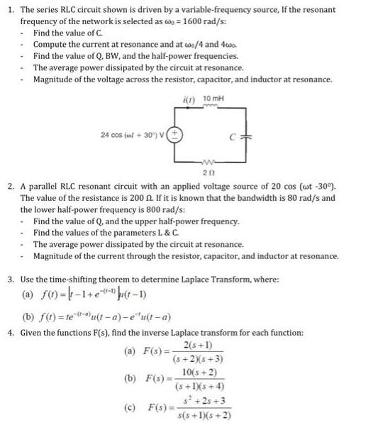
1. The series RLC circuit shown is driven by a variable-frequency source, If the resonant frequency of the network is selected as wo = 1600 rad/s: Find the value of C. Compute the current at resonance and at wo/4 and 4wo Find the value of Q, BW, and the half-power frequencies. The average power dissipated by the circuit at resonance. Magnitude of the voltage across the resistor, capacitor, and inductor at resonance. i(1) 10mH 24 cos (col+30) V( 2. A parallel RLC resonant circuit with an applied voltage source of 20 cos (wt -30%). The value of the resistance is 200 f2. If it is known that the bandwidth is 80 rad/s and the lower half-power frequency is 800 rad/s: Find the value of Q, and the upper half-power frequency. Find the values of the parameters L & C. The average power dissipated by the circuit at resonance. Magnitude of the current through the resistor, capacitor, and inductor at resonance. www 201 3. Use the time-shifting theorem to determine Laplace Transform, where: (a) f(t)=-1+e(t-1) (b) f(t)= teu(t-a)-eu(t-a) 4. Given the functions F(s), find the inverse Laplace transform for each function: (a) F(s)=- 2(s+1) (5+2)(5+3) 10(3+2) (s+1)(5+4) s +2s+3 s(s+1)(s+2) (b) F(s)= (c) F(s)=-
Step by Step Solution
3.51 Rating (164 Votes )
There are 3 Steps involved in it
1 a Given 0 1600 rads L 10 mH From the resonant frequency formula 02 1LC C 102L 116002 10x103 125600 ... View full answer

Get step-by-step solutions from verified subject matter experts