

Answered step by step
Verified Expert Solution
Question
1 Approved Answer
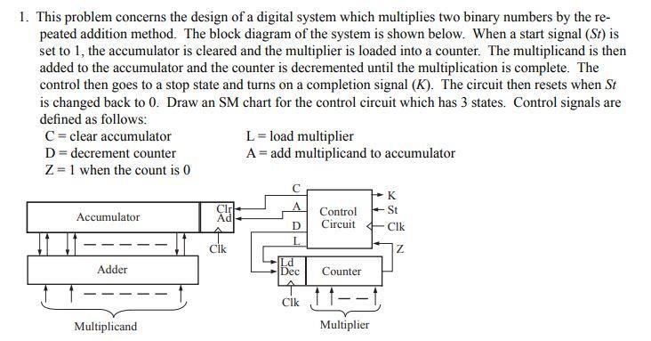
1. This problem concerns the design of a digital system which multiplies two binary numbers by the re- peated addition method. The block diagram of
Step by Step Solution
There are 3 Steps involved in it
Step: 1

Get Instant Access to Expert-Tailored Solutions
See step-by-step solutions with expert insights and AI powered tools for academic success
Step: 2

Step: 3
Ace Your Homework with AI
Get the answers you need in no time with our AI-driven, step-by-step assistance
Get Started
Murach's SQL Server 2012 For Developers
Authors: Bryan Syverson, Joel Murach, Mike Murach
1st Edition
1890774693, 9781890774691