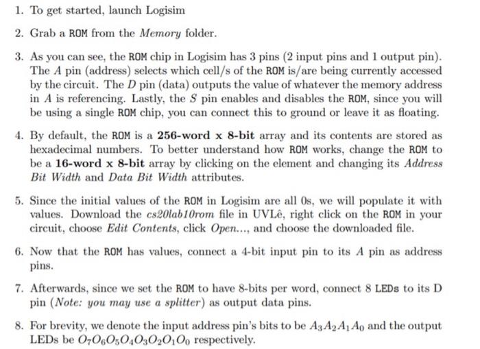
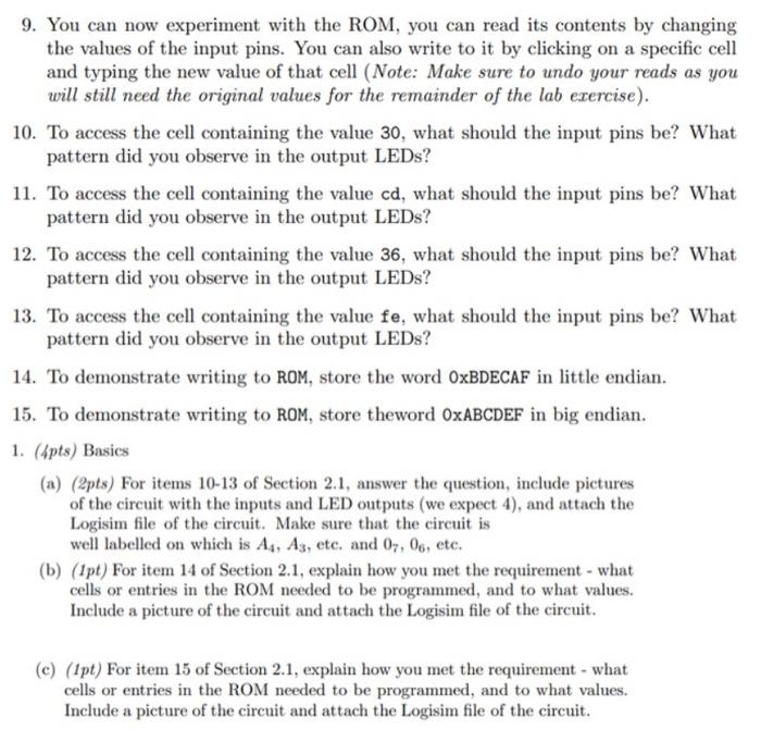
1. To get started, launch Logisim 2. Grab a ROM from the Memory folder. 3. As you can see, the ROM chip in Logisim has 3 pins (2 input pins and 1 output pin). The A pin (address) selects which cell/s of the ROM is/are being currently accessed by the circuit. The D pin (data) outputs the value of whatever the memory address in A is referencing. Lastly, the Spin enables and disables the ROM, since you will be using a single ROM chip, you can connect this to ground or leave it as floating 4. By default, the ROM is a 256-word x 8-bit array and its contents are stored as hexadecimal numbers. To better understand how ROM works, change the ROM to be a 16-word x 8-bit array by clicking on the element and changing its Address Bit Width and Data Bit Width attributes. 5. Since the initial values of the ROM in Logisim are all Os, we will populate it with values. Download the cs20lab10rom file in UVL, right click on the ROM in your circuit, choose Edit Contents, click Open..., and choose the downloaded file. 6. Now that the ROM has values, connect a 4-bit input pin to its A pin as address pins. 7. Afterwards, since we set the ROM to have 8-bits per word, connect 8 LEDs to its D pin (Note: you may use a splitter) as output data pins. 8. For brevity, we denote the input address pin's bits to be A3 A, A1 Ao and the output LEDs be 0-060304030,0,0, respectively, 19. You can now experiment with the ROM, you can read its contents by changing the values of the input pins. You can also write to it by clicking on a specific cell and typing the new value of that cell (Note: Make sure to undo your reads as you will still need the original values for the remainder of the lab exercise). 10. To access the cell containing the value 30, what should the input pins be? What pattern did you observe in the output LEDs? 11. To access the cell containing the value cd, what should the input pins be? What pattern did you observe in the output LEDs? 12. To access the cell containing the value 36, what should the input pins be? What pattern did you observe in the output LEDs? | 13. To access the cell containing the value fe, what should the input pins be? What pattern did you observe in the output LEDs? 14. To demonstrate writing to ROM, store the word OxBDECAF in little endian. | 15. "To demonstrate writing to ROM, store theword OxABCDEF in big endian. 1. (Apts) Basics (a) (2pts) For items 10-13 of Section 2.1, answer the question, include pictures of the circuit with the inputs and LED outputs (we expect 4), and attach the Logisim file of the circuit. Make sure that the circuit is well labelled on which is As, As, etc. and 07, 06, etc. (b) (1pt) For item 14 of Section 2.1, explain how you met the requirement - what cells or entries in the ROM needed to be programmed, and to what values. Include a picture of the circuit and attach the Logisim file of the circuit. (c) (Ipt) For item 15 of Section 2.1, explain how you met the requirement - what cells or entries in the ROM needed to be programmed, and to what values. Include a picture of the circuit and attach the Logisim file of the circuit. 1. To get started, launch Logisim 2. Grab a ROM from the Memory folder. 3. As you can see, the ROM chip in Logisim has 3 pins (2 input pins and 1 output pin). The A pin (address) selects which cell/s of the ROM is/are being currently accessed by the circuit. The D pin (data) outputs the value of whatever the memory address in A is referencing. Lastly, the Spin enables and disables the ROM, since you will be using a single ROM chip, you can connect this to ground or leave it as floating 4. By default, the ROM is a 256-word x 8-bit array and its contents are stored as hexadecimal numbers. To better understand how ROM works, change the ROM to be a 16-word x 8-bit array by clicking on the element and changing its Address Bit Width and Data Bit Width attributes. 5. Since the initial values of the ROM in Logisim are all Os, we will populate it with values. Download the cs20lab10rom file in UVL, right click on the ROM in your circuit, choose Edit Contents, click Open..., and choose the downloaded file. 6. Now that the ROM has values, connect a 4-bit input pin to its A pin as address pins. 7. Afterwards, since we set the ROM to have 8-bits per word, connect 8 LEDs to its D pin (Note: you may use a splitter) as output data pins. 8. For brevity, we denote the input address pin's bits to be A3 A, A1 Ao and the output LEDs be 0-060304030,0,0, respectively, 19. You can now experiment with the ROM, you can read its contents by changing the values of the input pins. You can also write to it by clicking on a specific cell and typing the new value of that cell (Note: Make sure to undo your reads as you will still need the original values for the remainder of the lab exercise). 10. To access the cell containing the value 30, what should the input pins be? What pattern did you observe in the output LEDs? 11. To access the cell containing the value cd, what should the input pins be? What pattern did you observe in the output LEDs? 12. To access the cell containing the value 36, what should the input pins be? What pattern did you observe in the output LEDs? | 13. To access the cell containing the value fe, what should the input pins be? What pattern did you observe in the output LEDs? 14. To demonstrate writing to ROM, store the word OxBDECAF in little endian. | 15. "To demonstrate writing to ROM, store theword OxABCDEF in big endian. 1. (Apts) Basics (a) (2pts) For items 10-13 of Section 2.1, answer the question, include pictures of the circuit with the inputs and LED outputs (we expect 4), and attach the Logisim file of the circuit. Make sure that the circuit is well labelled on which is As, As, etc. and 07, 06, etc. (b) (1pt) For item 14 of Section 2.1, explain how you met the requirement - what cells or entries in the ROM needed to be programmed, and to what values. Include a picture of the circuit and attach the Logisim file of the circuit. (c) (Ipt) For item 15 of Section 2.1, explain how you met the requirement - what cells or entries in the ROM needed to be programmed, and to what values. Include a picture of the circuit and attach the Logisim file of the circuit