

Question: 1.) Ulaby and Maharbiz problem 9.56 (for both second and third edition) Use Matlab to solve this problem. Spectral plots are the magnitude response plots
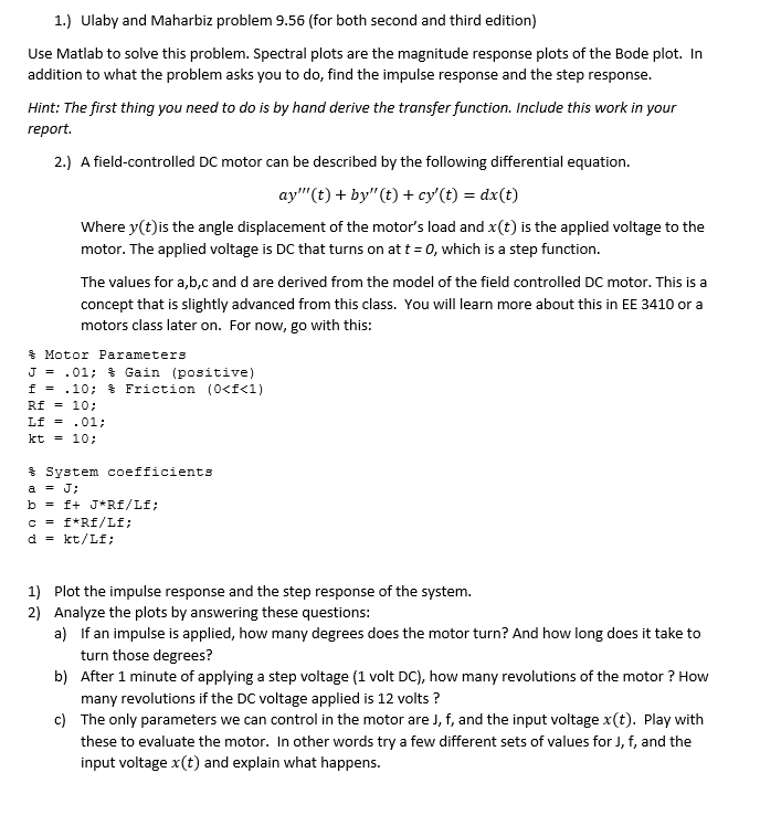
1.) Ulaby and Maharbiz problem 9.56 (for both second and third edition) Use Matlab to solve this problem. Spectral plots are the magnitude response plots of the Bode plot. In addition to what the problem asks you to do, find the impulse response and the step response Hint: The first thing you need to do is by hand derive the transfer function. Include this work in your report. 2.) A field-controlled DC motor can be described by the following differential equation. ay'"(t) + by"(t) + cy'(t) - dx(t) Where y(t)is the angle displacement of the motor's load and x(t) is the applied voltage to the motor. The applied voltage is DC that turns on at t- o, which is a step function. The values for a,b,c and d are derived from the model of the field controlled DC motor. This is a concept that is slightly advanced from this class. You will learn more about this in EE 3410 or a motors class later on. For now, go with this % Motor Parame ter3 J- .01; % Gain (positive) kt10: % System coefficients dkt/Lf: 1) 2) Plot the impulse response and the step response of the system. Analyze the plots by answering these questions: a) If an impulse is applied, how many degrees does the motor turn? And how long does it take to turn those degrees? After 1 minute of applying a step voltage (1 volt DC), how many revolutions of the motor ? How many revolutions if the DC voltage applied is 12 volts? The only parameters we can control in the motor are J, f, and the input voltage x(t). Play with these to evaluate the motor. In other words try a few different sets of values for J, f, and the input voltage x(t) and explain what happens. b) c) 1.) Ulaby and Maharbiz problem 9.56 (for both second and third edition) Use Matlab to solve this problem. Spectral plots are the magnitude response plots of the Bode plot. In addition to what the problem asks you to do, find the impulse response and the step response Hint: The first thing you need to do is by hand derive the transfer function. Include this work in your report. 2.) A field-controlled DC motor can be described by the following differential equation. ay'"(t) + by"(t) + cy'(t) - dx(t) Where y(t)is the angle displacement of the motor's load and x(t) is the applied voltage to the motor. The applied voltage is DC that turns on at t- o, which is a step function. The values for a,b,c and d are derived from the model of the field controlled DC motor. This is a concept that is slightly advanced from this class. You will learn more about this in EE 3410 or a motors class later on. For now, go with this % Motor Parame ter3 J- .01; % Gain (positive) kt10: % System coefficients dkt/Lf: 1) 2) Plot the impulse response and the step response of the system. Analyze the plots by answering these questions: a) If an impulse is applied, how many degrees does the motor turn? And how long does it take to turn those degrees? After 1 minute of applying a step voltage (1 volt DC), how many revolutions of the motor ? How many revolutions if the DC voltage applied is 12 volts? The only parameters we can control in the motor are J, f, and the input voltage x(t). Play with these to evaluate the motor. In other words try a few different sets of values for J, f, and the input voltage x(t) and explain what happens. b) c)
Step by Step Solution
There are 3 Steps involved in it

Get step-by-step solutions from verified subject matter experts