Question: 1. Using a table similar to that shown in Figure 3.6, calculate the product of the octal unsigned 6-bit integers 62 and 12 using the


![of each register on each step. [HINT]: Convert octal into binary. Each](https://dsd5zvtm8ll6.cloudfront.net/si.experts.images/questions/2024/09/66f45993783b0_74766f4599316cf0.jpg)
![octal number is 3-bits binary. [3 pts] Action Multiplicand Product/Multiplier 0 Initial](https://dsd5zvtm8ll6.cloudfront.net/si.experts.images/questions/2024/09/66f4599468ad2_74766f45993e6530.jpg)
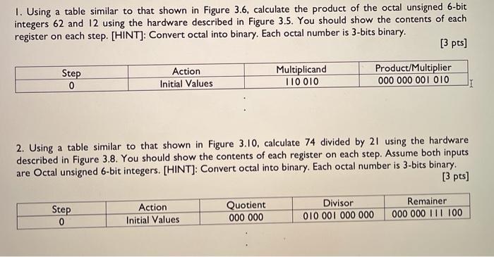
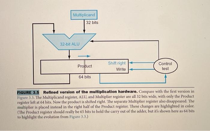
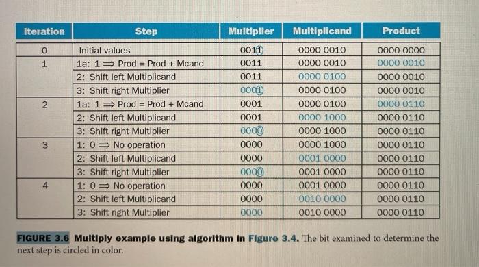
1. Using a table similar to that shown in Figure 3.6, calculate the product of the octal unsigned 6-bit integers 62 and 12 using the hardware described in Figure 3.5. You should show the contents of each register on each step. [HINT]: Convert octal into binary. Each octal number is 3-bits binary. [3 pts] Action Multiplicand Product/Multiplier 0 Initial Values T10010 000 000 001 010 II Step 2. Using a table similar to that shown in Figure 3.10, calculate 74 divided by 21 using the hardware described in Figure 3.8. You should show the contents of each register on each step. Assume both inputs are Octal unsigned 6-bit integers. [HINT): Convert octal into binary. Each octal number is 3-bits binary. [3 pts) Step 0 Action Initial Values Quotient 000 000 Divisor 010 001 000 000 Remainer 000 000 111 100 Multiplicand 32 bits 32-bit ALU Product Shift right Write Control test 64 bits FIGURE 3.5 Refined version of the multiplication hardware. Compare with the first version in Figure 3.3. The Multiplicand register, ALU, and Multiplier register are all 32 bits wide, with only the Product register left at 64 bits. Now the product is shifted right. The separate Multiplier register also disappeared. The multiplier is placed instead in the right half of the Product register. These changes are highlighted in color. (The Product register should really be 65 bits to hold the carry out of the adder, but it's shown here as 64 bits to highlight the evolution from Figure 3.3.) Iteration Step Multiplicand Product 0 1 2 Initial values 1a: 13 Prod = Prod + Mcand 2: Shift left Multiplicand 3: Shift right Multiplier 1a: 1 = Prod = Prod + Mcand 2: Shift left Multiplicand 3: Shift right Multiplier 1:0 = No operation 2: Sh left Multiplicand 3: Shift right Multiplier 1: 0 No operation 2: Shift left Multiplicand 3: Shift right Multiplier Multiplier 0011 0011 0011 0001 0001 0001 0000 0000 0000 0000 0000 0000 0000 0000 0010 0000 0010 0000 0100 0000 0100 0000 01.00 0000 1000 0000 1000 0000 1000 0001 0000 0001 0000 0001 0000 0010 0000 0010 0000 0000 0000 0000 0010 0000 0010 0000 0010 0000 0110 0000 0110 0000 0110 0000 0110 0000 0000 0110 0000 0110 0000 0110 0000 0110 3 4 FIGURE 3.6 Multiply example using algorithm in Figure 3.4. The bit examined to determine the next step is circled in color, Divisor Shift right 64 bits 64-bit ALU Quotient Shift left 32 bits Remainder Control test Write 64 bits FIGURE 3.8 First version of the division hardware. The Divisor register, ALU, and Remainder register are all 64 bits wide, with only the Quotient register being 32 bits. The 32-bit divisor starts in the left half of the Divisor register and is shifted right 1 bit each iteration. The remainder is initialized with the dividend. Control decides when to shift the Divisor and Quotient registers and when to write the new value into the Remainder register. Iteration Step Quotient Divisor Remainder 0 1 2 Initial values 1: Rem = Rem - Div 2b: Rem
Step by Step Solution
There are 3 Steps involved in it

Get step-by-step solutions from verified subject matter experts


