

Question: 11:30 PM Fri 6 Oct Submit Verilog Assignment #1 _ Gradescope.pdf LI 02.1 5 Points Consider a circuit model referred to as MOD1 whose
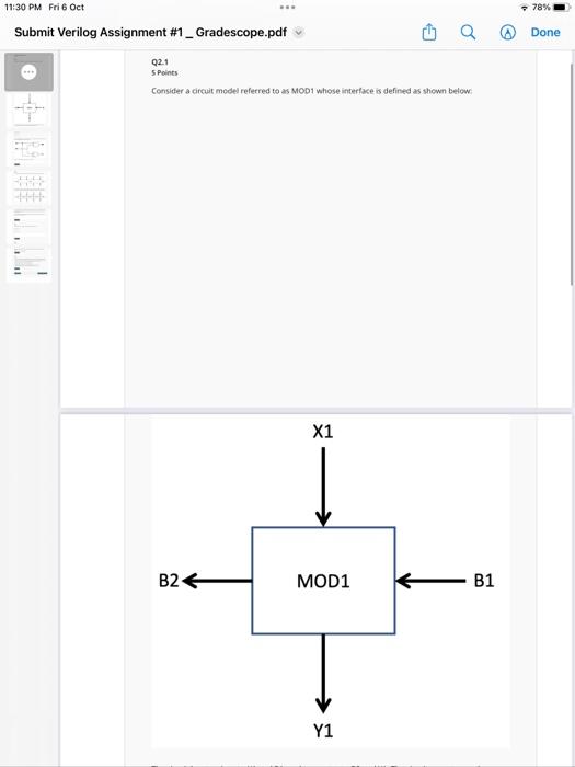
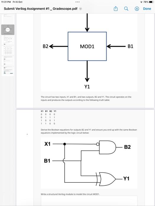
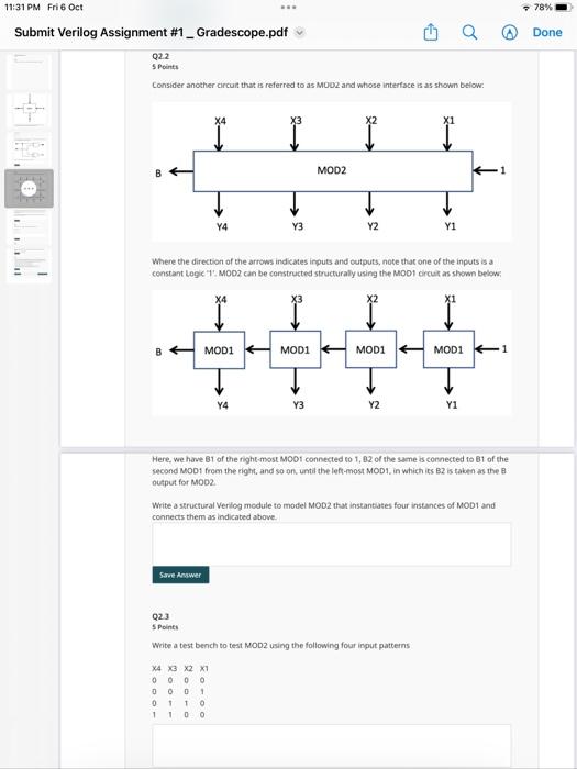

11:30 PM Fri 6 Oct Submit Verilog Assignment #1 _ Gradescope.pdf LI 02.1 5 Points Consider a circuit model referred to as MOD1 whose interface is defined as shown below: B24 X1 MOD1 Y1 B1 78% Done 11:31 PM Fri 6 Oct Submit Verilog Assignment #1 _ Gradescope.pdf 11 B24 X1 81 82 V1 0 0 0 0 0111 1001 1100 MOD1 Y1 The circuit has two inputs, X1 and B1, and two outputs, 82 and Y1. The circuit operates on the inputs and produces the outputs according to the following truth table: X1 B1 O Derive the Boolean equations for outputs 82 and Y1 and ensure you end up with the same Boolean equations implemented by the logic circuit below: D- B1 Write a structural Verilog module to model the circuit MOD1. B2 Y1 78% Done 11:31 PM Fri 6 Oct Submit Verilog Assignment #1 _ Gradescope.pdf Q2.2 5 Points Consider another circuit that is referred to as MOD2 and whose interface is as shown below: B X4 Y4 Save Answer *** X4 MOD1 4 X3 X2 X1 0000 0001 0110 1 1 0 0 Y4 X3 Y3 Where the direction of the arrows indicates inputs and outputs, note that one of the inputs is a constant Logic "1. MOD2 can be constructed structurally using the MOD1 circuit as shown below: MOD1 MOD2 Y3 g Y2 MOD1 Y2 Y1 Q2.3 5 Points Write a testbench to test MOD2 using the following four input patterns Here, we have B1 of the right-most MOD1 connected to 1,82 of the same is connected to 81 of the second MOD1 from the right, and so on, until the left-most MOD1, in which its B2 is taken as the B output for MOD2. Write a structural Verilog module to model MOD2 that instantiates four instances of MOD1 and connects them as indicated above. 1 MOD11 Y1 78% Done 11:31 PM Fri 6 Oct Submit Verilog Assignment #1 _ Gradescope.pdf + IKE 6 of 6 Save Answer Q2.3 5 Points Write a te atest bench to test MODZ using the following four input patterns X4 X3 X2 X1 0000 0001 0 110 1 100 Save Answer Q2.4 5 Points Please select file Select file) Save Answer www Simulate your test bench and attach a snapshot of the generated waveform using the button below. Q2.5 1 Point Save Answer A Save All Answers What do you observe about the input/output relationship of Circuit MOD2? Hint: Consider X-X4, X3, X2, X1 as the bits of an unsigned 4-bit binary integer where X4 is the most significant bit (MSB), and Y-Y4, Y3, V2, Y1 as the bits of an unsigned 4-bit binary integer where Y4 is the MSB. OMOD2 increments X by 1, and 8 is the final carryout bit OMOD2 decrements X by 1, and B is the final borrow bit OMOD2 counts the number of 1s in X and B indicates if X has any Os or not OMODZ counts the number of Os in X, and B indicates if X has any 1s or not Q Submit & View Submission> 78% Done
Step by Step Solution
There are 3 Steps involved in it
The skin friction coefficient Cf for a laminar boundary ... View full answer

Get step-by-step solutions from verified subject matter experts