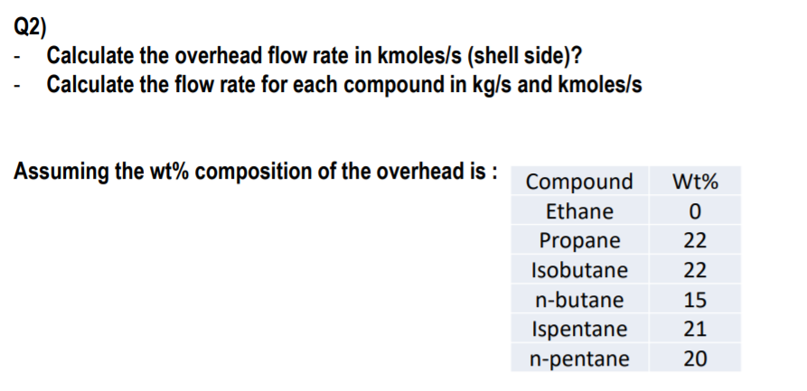
Question: 1)solve all questions either i will dislike Data Data Q2) Calculate the overhead flow rate in kmoles/s (shell side)? Calculate the flow rate for each
1)solve all questions either i will dislike
 Data
Data
 Data
Data
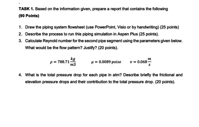
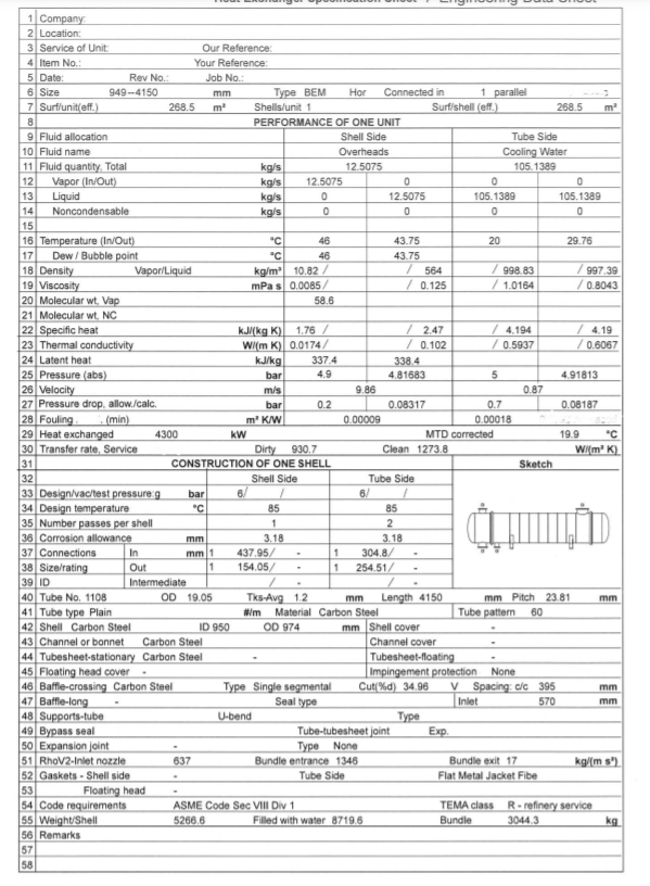
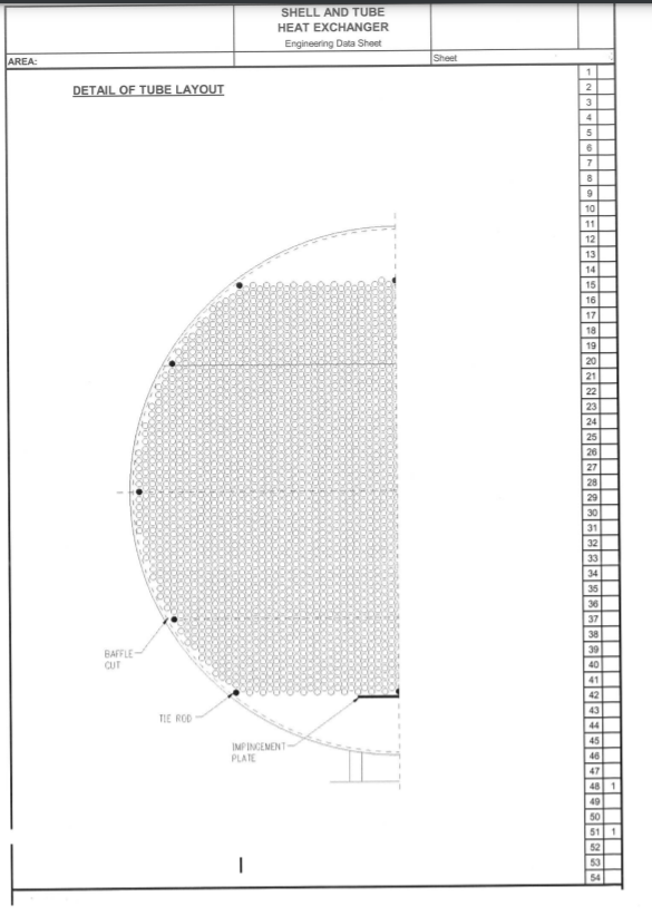
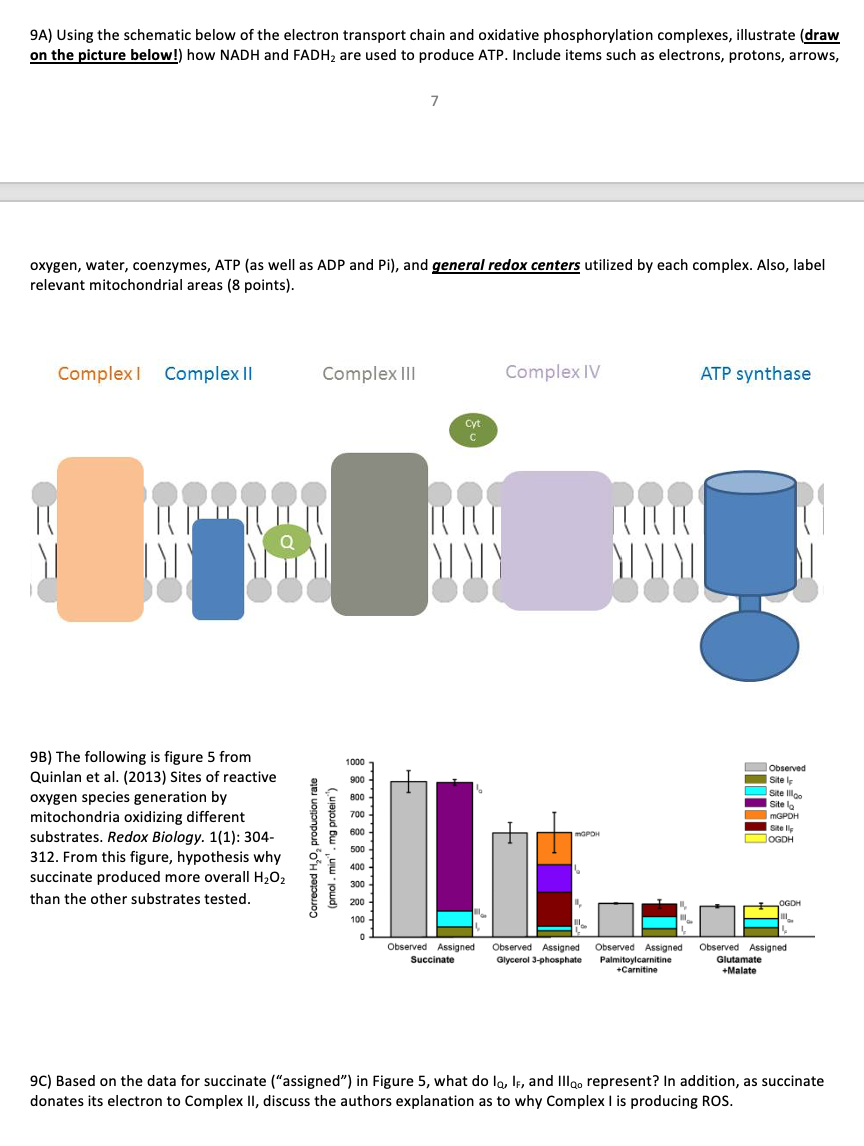
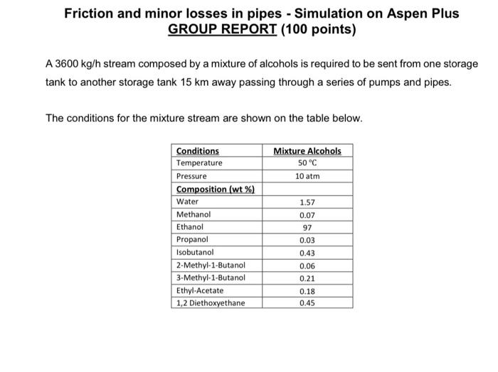
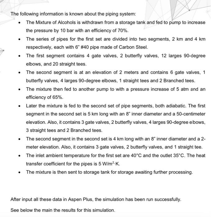
Q2) Calculate the overhead flow rate in kmoles/s (shell side)? Calculate the flow rate for each compound in kg/s and kmoles/s Assuming the wt% composition of the overhead is : Compound Ethane Propane Isobutane n-butane Ispentane n-pentane wt% 0 22 22 15 21 20 OO oo 1 Company 2 Location: 3 Service of Unit Our Reference 4 Item No.: Your Reference: 5 Date: Rev No.: Job No.: 6 Size 949-4150 mm Type BEM Hor Connected in 1 parallel 2 7 Surf/unit/eff.) 268.5 m Shells/unit 1 Surf/shell (off) 268.5 m 8 PERFORMANCE OF ONE UNIT 9 Fluid allocation Shell Side Tube Side 10 Fluid name Overheads Cooling Water 11 Fluid quantity Total kg/s 12.5075 105.1389 12 Vapor (In/Out) kg/s 12.5075 0 0 0 13 Liquid kg/s 12.5075 105.1389 105.1389 14 Noncondensable kg/s 0 0 0 15 16 Temperature (In/Out) 46 43.75 20 29.76 17 Dew/ Bubble point 46 43.75 18 Density Vapor/Liquid kg/m 10.82 / 564 998.83 / 997 39 19 Viscosity mPas 0.0085 0.125 / 1.0164 /0.8043 20 Molecular wt Vap 58.6 21 Molecular wt. NC 22 Specific heat kJ/(kg) 1.76 / / 2.47 4.194 / 4.19 23 Thermal conductivity Wim K) 0.0174/ / 0.102 / 0.5937 / 0.6067 24 Latent heat kJ/kg 337.4 338.4 25 Pressure (abs) bar 4.9 4.81683 5 4.91813 26 Velocity m/s 9.86 0.87 27 Pressure drop, allow./calc. bar 0.2 0.08317 0.7 0.08187 28 Fouling min m' KW 0.00009 0.00018 29 Heat exchanged 4300 kW MTD corrected 19.9 "C 30 Transfer rate, Service Dirty 930.7 Clean 1273,8 WI( mK) 31 CONSTRUCTION OF ONE SHELL Sketch 32 Shell Side Tube Side 33 Design/vac/test pressure 9 bar 6 1 6/ / 34 Design temperature "C 85 85 35 Number passes per shell 1 2 36 Corrosion allowance mm 3.18 3.18 37 Connections In mm 1 437.95 1 3048/ 38 Size/rating Out 1 154.05/ 1 254.51/ 39 ID Intermediate 40 Tube No. 1108 OD 19.05 Tks Avg 12 mm Length 4150 mm Pitch 23.81 mm 41 Tube type Plain Material Carbon Steel Tube pattern 60 42 Shell Carbon Steel ID 950 OD 974 mm Shell cover 43 Channel or bonnet Carbon Steel Channel cover 44 Tubesheet-stationary Carbon Steel Tubesheet-floating 45 Floating head cover Impingement protection None 46 Baffle-crossing Carbon Steel Type Single segmental Cut/%d) 34.96 V Spacing: c/c 395 mm 47 Baffle-long Seal type 570 mm 48 Supports-tube U-bend Type 49 Bypass seal Tube-tubesheet joint Exp 50 Expansion joint Type None 51 RhoV2-Inlet nozzle 637 Bundle entrance 1346 Bundle exit 17 kg/(ms) 52 Gaskets - Shell side Tube Side Flat Metal Jacket Fibe 53 Floating head 54 Code requirements ASME Code Sec VIII Div 1 TEMA class R.refinery service 55 Weight/Shell 5266.6 Filled with water 8719.6 Bundle 30443 kg 56 Remarks 57 58 Inlet SHELL AND TUBE HEAT EXCHANGER Engineering Data Sheet AREA: Sheet DETAIL OF TUBE LAYOUT 1 2 3 4 5 6 7 8 9 10 11 12 13 14 15 16 17 18 19 20 21 22 23 24 25 26 27 28 29 30 31 32 33 34 35 36 37 38 39 40 41 42 43 44 45 46 47 481 49 50 511 52 53 54 BAFFLE CUT TIE ROD IMPINGEMENT PLATE 1 1 +++ Fe Feoht Fe(OH 5 Fe(OH)2(a) Eh (volts) All Data 2019 Data Fett Fe(OH) FeOH 25C 0 2 N 10 12 14 8 . 9A) Using the schematic below of the electron transport chain and oxidative phosphorylation complexes, illustrate (draw on the picture below!) how NADH and FADH2 are used to produce ATP. Include items such as electrons, protons, arrows, 7 oxygen, water, coenzymes, ATP (as well as ADP and Pi), and general redox centers utilized by each complex. Also, label relevant mitochondrial areas (8 points). Complex Complex 11 Complex III Complex IV ATP synthase Cyt C MT MI TITI MUY vo 1000 900 800 9B) The following is figure 5 from Quinlan et al. (2013) Sites of reactive oxygen species generation by mitochondria oxidizing different substrates. Redox Biology. 1(1): 304- 312. From this figure, hypothesis why succinate produced more overall H2O2 than the other substrates tested. Observed Site Site Illa Site lo MGPOH Sitell OGDH 700 600 Corrected H,, production rate (pmol. min. mg protein 500 I 400 OGDH 100 Observed Assigned Succinate Observed Assigned Observed Assigned Glycerol 3-phosphate Palmitoylcarnitine +Carnitine Observed Assigned Glutamate +Malate 9C) Based on the data for succinate ("assigned") in Figure 5, what do lo, IF, and Illgo represent? In addition, as succinate donates its electron to Complex II, discuss the authors explanation as to why Complex I is producing ROS. Friction and minor losses in pipes - Simulation on Aspen Plus GROUP REPORT (100 points) A 3600 kg/h stream composed by a mixture of alcohols is required to be sent from one storage tank to another storage tank 15 km away passing through a series of pumps and pipes. The conditions for the mixture stream are shown on the table below. Mixture Alcohols 50C 10 atm Conditions Temperature Pressure Composition (wt %) Water Methanol Ethanol Propanol Isobutanol 2-Methyl-1-Butanol 3-Methyl-1-Butanol Ethyl-Acetate 1,2 Diethoxyethane 1.57 0.07 97 0.03 0.43 0.06 0.21 0.18 0.45 The following information is known about the piping system: The Mixture of Alcohols is withdrawn from a storage tank and fed to pump to increase the pressure by 10 bar with an efficiency of 70%. The series of pipes for the first set are divided into two segments, 2 km and 4 km respectively, each with 6" #40 pipe made of Carbon Steel. The first segment contains 4 gate valves, 2 butterfly valves, 12 larges 90-degree elbows, and 20 straight tees. The second segment is at an elevation of 2 meters and contains 6 gate valves, 1 butterfly valves, 4 larges 90-degree elbows, 1 straight tees and 2 Branched tees. The mixture then fed to another pump to with a pressure increase of 5 atm and an efficiency of 65%. Later the mixture is fed to the second set of pipe segments, both adiabatic. The first segment in the second set is 5 km long with an 8" inner diameter and a 50-centimeter elevation. Also, it contains 3 gate valves, 2 butterfly valves, 4 larges 90-degree elbows, 3 straight tees and 2 Branched tees. The second segment in the second set is 4 km long with an 8" inner diameter and a 2- meter elevation. Also, it contains 3 gate valves, 2 butterfly valves, and 1 straight tee. The inlet ambient temperature for the first set are 40C and the outlet 35C. The heat transfer coefficient for the pipes is 5 W/m2.K. The mixture is then sent to storage tank for storage awaiting further processing. After input all these data in Aspen Plus, the simulation has be run successfully. See below the main the results for this simulation. TASK 1. Based on the information given, prepare a report that contains the following (90 Points) 1. Draw the piping system flowsheet (use PowerPoint, Visio or by handwriting) (25 points) 2. Describe the process to run this piping simulation in Aspen Plus (25 points). 3. Calculate Reynold number for the second pipe segment using the parameters given below. What would be the flow pattern? Justify? (20 points). P = 788.71 kg u = 0.0089 poise m v = 0.068 m3 4. What is the total pressure drop for each pipe in atm? Describe briefly the frictional and elevation pressure drops and their contribution to the total pressure drop. (20 points)
Step by Step Solution
There are 3 Steps involved in it

Get step-by-step solutions from verified subject matter experts


