Answered step by step
Verified Expert Solution
Question
1 Approved Answer
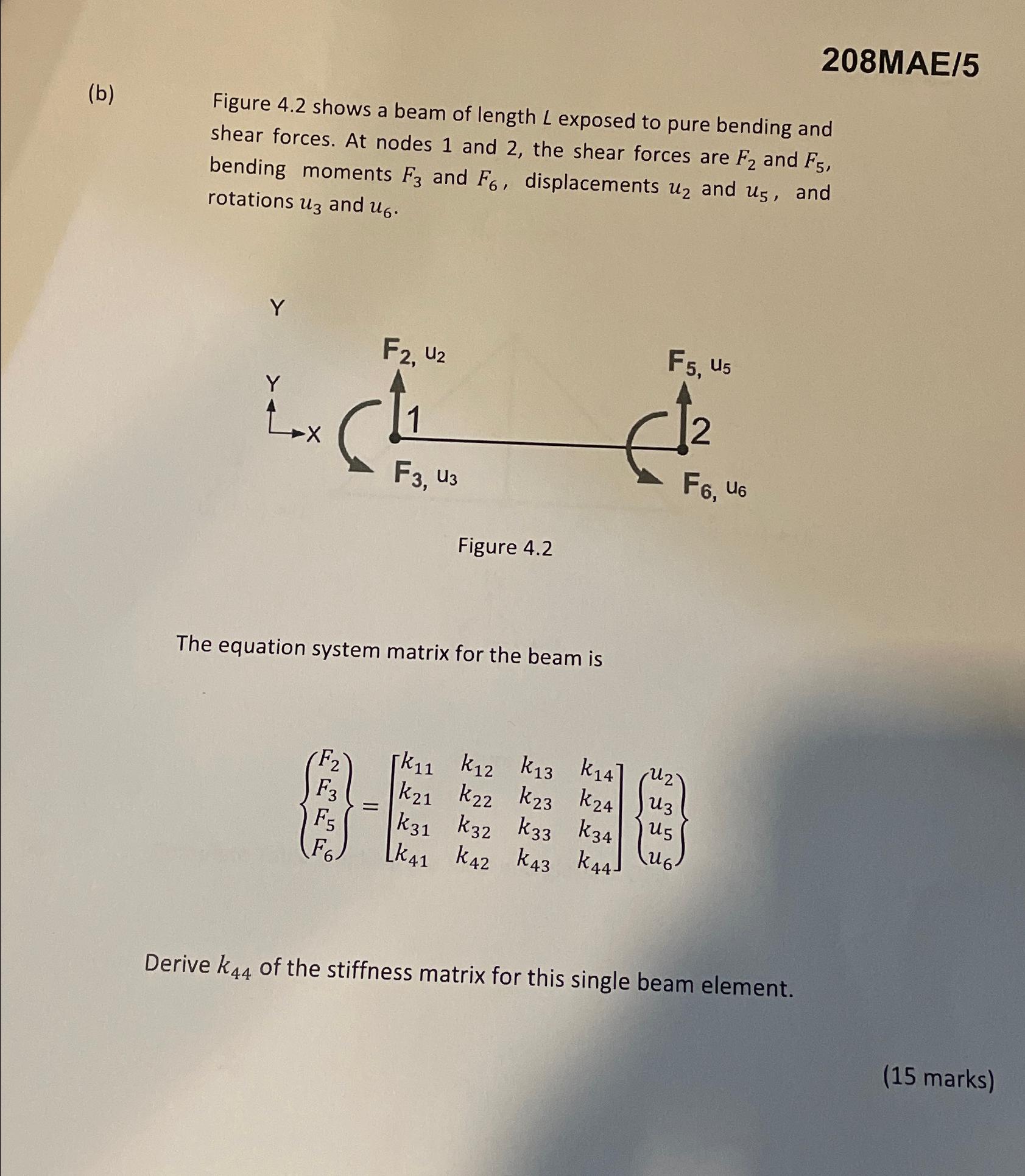
2 0 8 MAE / 5 ( b ) Figure 4 . 2 shows a beam of length L exposed to pure bending and shear
MAE
b Figure shows a beam of length exposed to pure bending and shear forces. At nodes and the shear forces are and bending moments and displacements and and rotations and
The equation system matrix for the beam is
Derive of the stiffness matrix for this single beam element.
marks

Step by Step Solution
There are 3 Steps involved in it
Step: 1

Get Instant Access to Expert-Tailored Solutions
See step-by-step solutions with expert insights and AI powered tools for academic success
Step: 2

Step: 3

Ace Your Homework with AI
Get the answers you need in no time with our AI-driven, step-by-step assistance
Get Started


