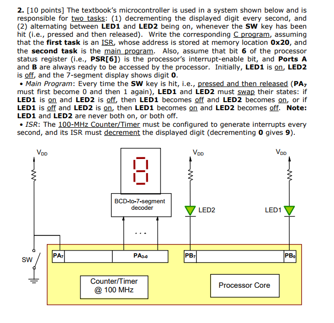
2. [10 points] The textbook's microcontroller is used in a system shown below and is responsible for two tasks: (1) decrementing the displayed digit every second, and (2) alternating between LED1 and LED2 being on, whenever the SW key has been hit (i.e., pressed and then released). Write the corresponding C program, assuming that the first task is an ISR, whose address is stored at memory location 0x20, and the second task is the main program. Also, assume that bit 6 of the processor status register (i.e., PSR[6]) is the processor's interrupt-enable bit, and Ports A and B are always ready to be accessed by the processor. Initially, LED1 is on, LED2 is off, and the 7-segment display shows digit 0 Main Program: Every time the SW key is hit, i.e., pressed and then released (PA7 must first become 0 and then 1 again), LED1 and LED2 must swap their states: if LED1 is on and LED2 is off, then LED1 becomes off and LED2 becomes on, or if LED1 is off and LED2 is on, then LED1 becomes on and LED2 becomes off. Note: LED1 and LED2 are never both on, or both off . ISR: The second, and its ISR must decrement the displayed digit (decrementing 0 gives 9) 5 5 must be configured to generate interrupts every BCD-to-7-segment decoder LED2 LED1 PA3- PB PB SW Counter/Timer @ 100 MHz Processor Core 2. [10 points] The textbook's microcontroller is used in a system shown below and is responsible for two tasks: (1) decrementing the displayed digit every second, and (2) alternating between LED1 and LED2 being on, whenever the SW key has been hit (i.e., pressed and then released). Write the corresponding C program, assuming that the first task is an ISR, whose address is stored at memory location 0x20, and the second task is the main program. Also, assume that bit 6 of the processor status register (i.e., PSR[6]) is the processor's interrupt-enable bit, and Ports A and B are always ready to be accessed by the processor. Initially, LED1 is on, LED2 is off, and the 7-segment display shows digit 0 Main Program: Every time the SW key is hit, i.e., pressed and then released (PA7 must first become 0 and then 1 again), LED1 and LED2 must swap their states: if LED1 is on and LED2 is off, then LED1 becomes off and LED2 becomes on, or if LED1 is off and LED2 is on, then LED1 becomes on and LED2 becomes off. Note: LED1 and LED2 are never both on, or both off . ISR: The second, and its ISR must decrement the displayed digit (decrementing 0 gives 9) 5 5 must be configured to generate interrupts every BCD-to-7-segment decoder LED2 LED1 PA3- PB PB SW Counter/Timer @ 100 MHz Processor Core