Question
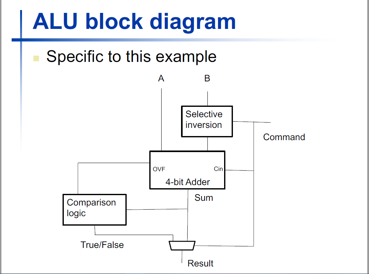
2. An ALU that takes two 4-bit inputs, A and B, and then generates a 4-bit result, S, based on a 2-bit command, F1F0. The

2. An ALU that takes two 4-bit inputs, A and B, and then generates a 4-bit result, S, based on a 2-bit command, F1F0. The meaning of the 2-bit command is
if F1F0 == 00 then the ALU computes the sum (S=A+B)
if F1F0 == 01 then it computes the difference (S=A-B)
if F1F0 == 11 then it generates a true/false indication of whether A
We didnt use a command encoding of 10. So lets say we want to add that encoding and generate the true indication of 0001 if A>B, and the false indication of 0000 if A is not greater than B.
(a) We have a control signal called Subtract that, when asserted, causes operand B to be inverted and causes a carry-in of 1 to be fed into the ripple carry adder. What does the logic for this Subtract signal need to be now given the fact that F1F0 could be both 11 and 10 to mean that we want to do a comparison (and not just 11 as it is above)?
(b) Assuming we have correctly controlled our ripple carry adder to perform a subtraction, the sign bit of the result plays a role in determining the comparison result. If were trying to determine if A is greater than B, there are two reasons why we cant just look at the sign bit to see if its 0. What are those two reasons?
(c) Assuming we have signals called Zero, which asserts if all 4 sum bits out of the ripple carry adder are 0, and LessThan, which we defined as the XOR of the overflow condition and the sign bit of the result computed by the ripple carry adder, how can we use these two signals to generate a third signal, called GreaterThan, that asserts if A is greater than B?
(d) Given the command encodings defined above, if F1=1 then the LSB of the ALU result, S0, becomes a true/false flag that corresponds to the type of comparison identified by F0. Assuming we are using a 2:1 mux to generate S0, with F1 as the mux select, the connection to data port 0 of this mux would just be bit0 of the result computed by the ripple carry adder. But the connection to data port 1 of the mux needs to be the correct true/false flag. Lets call this signal CR, for Comparison Result. Generate the truth table for CR as a function of any signals that you believe to be relevant to correctly generate the behavior of this signal.
| ALU block diagram Specific to this example A B Selective inversion Command OVE Cin 4-bit Adder Sum Comparison logic True/False ResultStep by Step Solution
There are 3 Steps involved in it
Step: 1

Get Instant Access to Expert-Tailored Solutions
See step-by-step solutions with expert insights and AI powered tools for academic success
Step: 2

Step: 3

Ace Your Homework with AI
Get the answers you need in no time with our AI-driven, step-by-step assistance
Get Started


