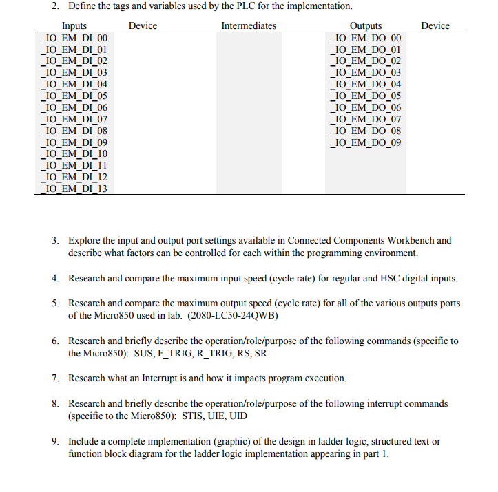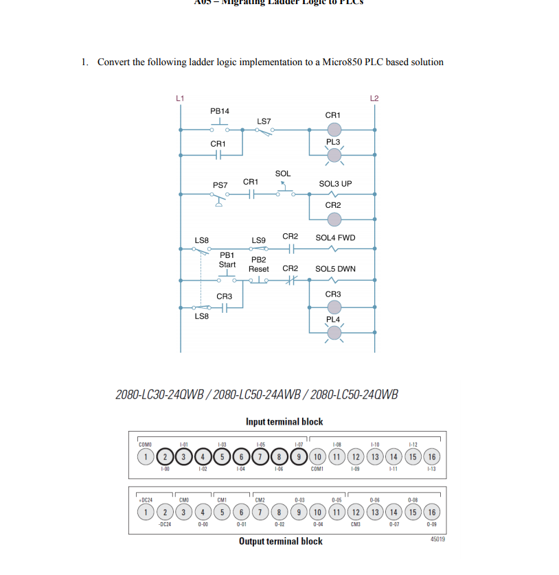

2. Define the tags and variables used by the PLC for the implementation. Inputs Device Intermediates Outputs Device IO_EM_DO 00 IOEM DO 01 IO_EM_Do_02 IO_EM_DO 03 IO_EM_DO 04 IO_EM_DO 05 IOEM DO 06 IO_EM_DO 07 IO_EM_DO 08 IO_EM_DO 09 IO_EM DI 00 IO_EM_DI_01 IO EM DI 02 IO_EM_DI 03 IO EM DI 04 IO EM DI 05 IO_EM_DI 06 IO EM DI 07 IO EM DI 08 IO EM DI 09 IO EM DI 10 IO_EM_DI_11 IO EM DI 12 IO EM DI13 3. Explore the input and output port settings available in Connected Components Workbench and describe what factors can be controlled for each within the programming environment. Research and compare the maximum input speed (cycle rate) for regular and HSC digital inputs Research and compare the maximum output speed (cycle rate) for all of the various outputs ports 4. 5. of the Micro850 used in lab. (2080-LC50-24QWB) 6. Research and briefly describe the operation/role/purpose of the following commands (specific to the Micro850): SUS, F_TRIG, R_TRIG, RS, SR Research what an Interrupt is and how it impacts program execution. Research and briefly describe the operation/role/purpose of the following interrupt commands 7. 8. (specific to the Micro850): STIS, UIE, UID 9. Include a complete implementation (graphic) of the design in ladder logic, structured text or function block diagram for the ladder logic implementation appearing in part 1 2. Define the tags and variables used by the PLC for the implementation. Inputs Device Intermediates Outputs Device IO_EM_DO 00 IOEM DO 01 IO_EM_Do_02 IO_EM_DO 03 IO_EM_DO 04 IO_EM_DO 05 IOEM DO 06 IO_EM_DO 07 IO_EM_DO 08 IO_EM_DO 09 IO_EM DI 00 IO_EM_DI_01 IO EM DI 02 IO_EM_DI 03 IO EM DI 04 IO EM DI 05 IO_EM_DI 06 IO EM DI 07 IO EM DI 08 IO EM DI 09 IO EM DI 10 IO_EM_DI_11 IO EM DI 12 IO EM DI13 3. Explore the input and output port settings available in Connected Components Workbench and describe what factors can be controlled for each within the programming environment. Research and compare the maximum input speed (cycle rate) for regular and HSC digital inputs Research and compare the maximum output speed (cycle rate) for all of the various outputs ports 4. 5. of the Micro850 used in lab. (2080-LC50-24QWB) 6. Research and briefly describe the operation/role/purpose of the following commands (specific to the Micro850): SUS, F_TRIG, R_TRIG, RS, SR Research what an Interrupt is and how it impacts program execution. Research and briefly describe the operation/role/purpose of the following interrupt commands 7. 8. (specific to the Micro850): STIS, UIE, UID 9. Include a complete implementation (graphic) of the design in ladder logic, structured text or function block diagram for the ladder logic implementation appearing in


