

Answered step by step
Verified Expert Solution
Question
1 Approved Answer
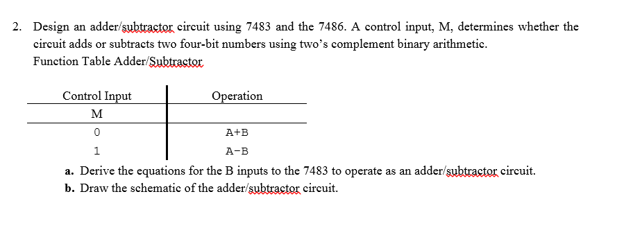
2. Design an adder/subtractor circuit using 7483 and the 7486. A control input, M, determines whether the circuit adds or subtracts two four-bit numbers using
Step by Step Solution
There are 3 Steps involved in it
Step: 1

Get Instant Access to Expert-Tailored Solutions
See step-by-step solutions with expert insights and AI powered tools for academic success
Step: 2

Step: 3
Ace Your Homework with AI
Get the answers you need in no time with our AI-driven, step-by-step assistance
Get Started
Parallel Database Systems Prisma Workshop Noordwijk The Netherlands September 24 26 1990 Proceedings Lncs 503
Authors: Pierre America
1st Edition
0387541322, 978-0387541327