

Answered step by step
Verified Expert Solution
Question
1 Approved Answer
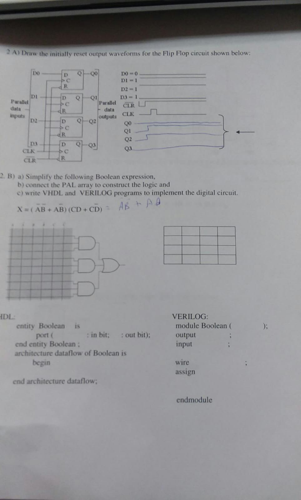
2) Draw the initially reset output waveforms for the Flip Flop circuit shown below: DO-0 Di- 1 D2-1 D3-1 Parallel data nputs p2 CLR CLK
Step by Step Solution
There are 3 Steps involved in it
Step: 1

Get Instant Access to Expert-Tailored Solutions
See step-by-step solutions with expert insights and AI powered tools for academic success
Step: 2

Step: 3
Ace Your Homework with AI
Get the answers you need in no time with our AI-driven, step-by-step assistance
Get Started
Practical Issues In Database Management A Refernce For The Thinking Practitioner
Authors: Fabian Pascal
1st Edition
0201485559, 978-0201485554