

Question
2. Given the following code: module clock_gate(input wire clk, enable, din, set,output reg dout); always @(negedge clk or posedge set) begin if (set) dout else
2. Given the following code:
module clock_gate(input wire clk, enable, din, set,output reg dout);
always @(negedge clk or posedge set) begin
if (set)
dout
else if (enable)
dout
end
endmodule
a. Synthesize to insert clock gating circuitry. (15pts)
b. Instantiate the original code and netlist in a testbench and test them in parallel to verify identical functionality. Compare the output of both models and increment an error counter if they differ. Turn in your testbench code, the netlist, and a waveform showing the I/O of the original code, I/O of the netlist, and an error counter. (20pts)
The testbench will look like:
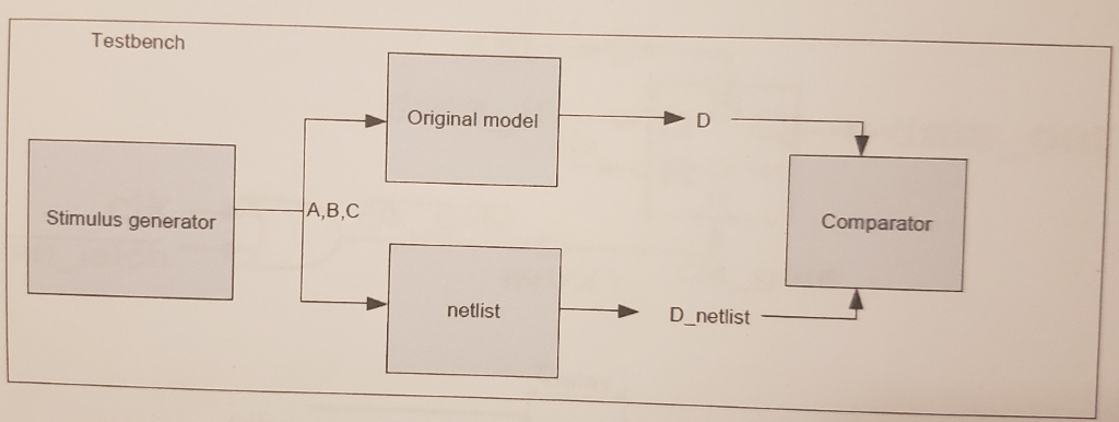
c. From the simulation in part b. what is the delay from a negative edge on input clk to a falling edge on output D_netlist? Show the delay in a simulation waveform. (10pts)
Testbench Original model A,B,C Comparator Stimulus generator netlist D_netlist Testbench Original model A,B,C Comparator Stimulus generator netlist D_netlistStep by Step Solution
There are 3 Steps involved in it
Step: 1

Get Instant Access to Expert-Tailored Solutions
See step-by-step solutions with expert insights and AI powered tools for academic success
Step: 2

Step: 3
Ace Your Homework with AI
Get the answers you need in no time with our AI-driven, step-by-step assistance
Get Started
Database Systems For Advanced Applications 17th International Conference Dasfaa 2012 International Workshops Flashdb Items Snsm Sim Dqdi Busan South Korea April 2012 Proceedings Lncs 7240
Authors: Hwanjo Yu ,Ge Yu ,Wynne Hsu ,Yang-Sae Moon ,Rainer Unland ,Jaesoo Yoo
2012th Edition