

Answered step by step
Verified Expert Solution
Question
1 Approved Answer
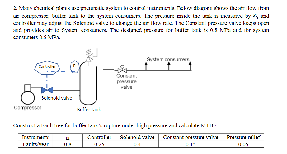
2. Many chemical plants use pneumatic system to control instruments. Below diagram shows the air flow from air compressor, buffer tank to the system consumers.
Step by Step Solution
There are 3 Steps involved in it
Step: 1

Get Instant Access to Expert-Tailored Solutions
See step-by-step solutions with expert insights and AI powered tools for academic success
Step: 2

Step: 3
Ace Your Homework with AI
Get the answers you need in no time with our AI-driven, step-by-step assistance
Get Started
Separation process principles
Authors: J. D. Seader
2nd Edition
471464805, 978-0471464808