

Answered step by step
Verified Expert Solution
Question
1 Approved Answer
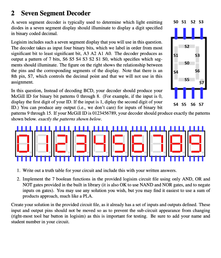
2 Seven Segment Decoder A seven segment decoder is typically used to determine which light emitting diodes in a seven segment display should illuminate to
Step by Step Solution
There are 3 Steps involved in it
Step: 1

Get Instant Access to Expert-Tailored Solutions
See step-by-step solutions with expert insights and AI powered tools for academic success
Step: 2

Step: 3
Ace Your Homework with AI
Get the answers you need in no time with our AI-driven, step-by-step assistance
Get Started
Big Data Systems A 360-degree Approach
Authors: Jawwad ShamsiMuhammad Khojaye
1st Edition
0429531575, 9780429531576