

Answered step by step
Verified Expert Solution
Question
1 Approved Answer
2. Software Requirement In this task, you will be using the Logisim circuit drawing software to create a circuit for the problem specified in this
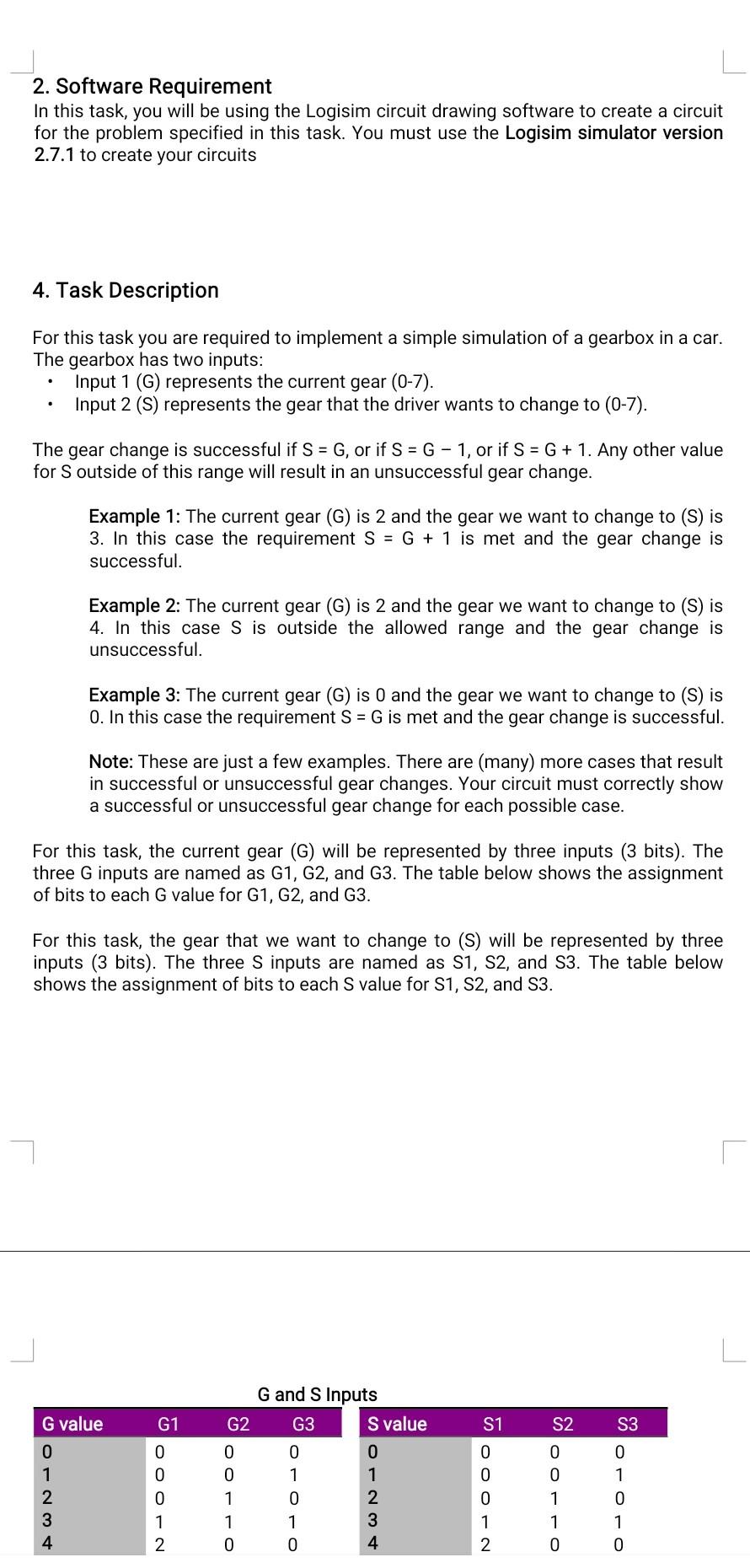
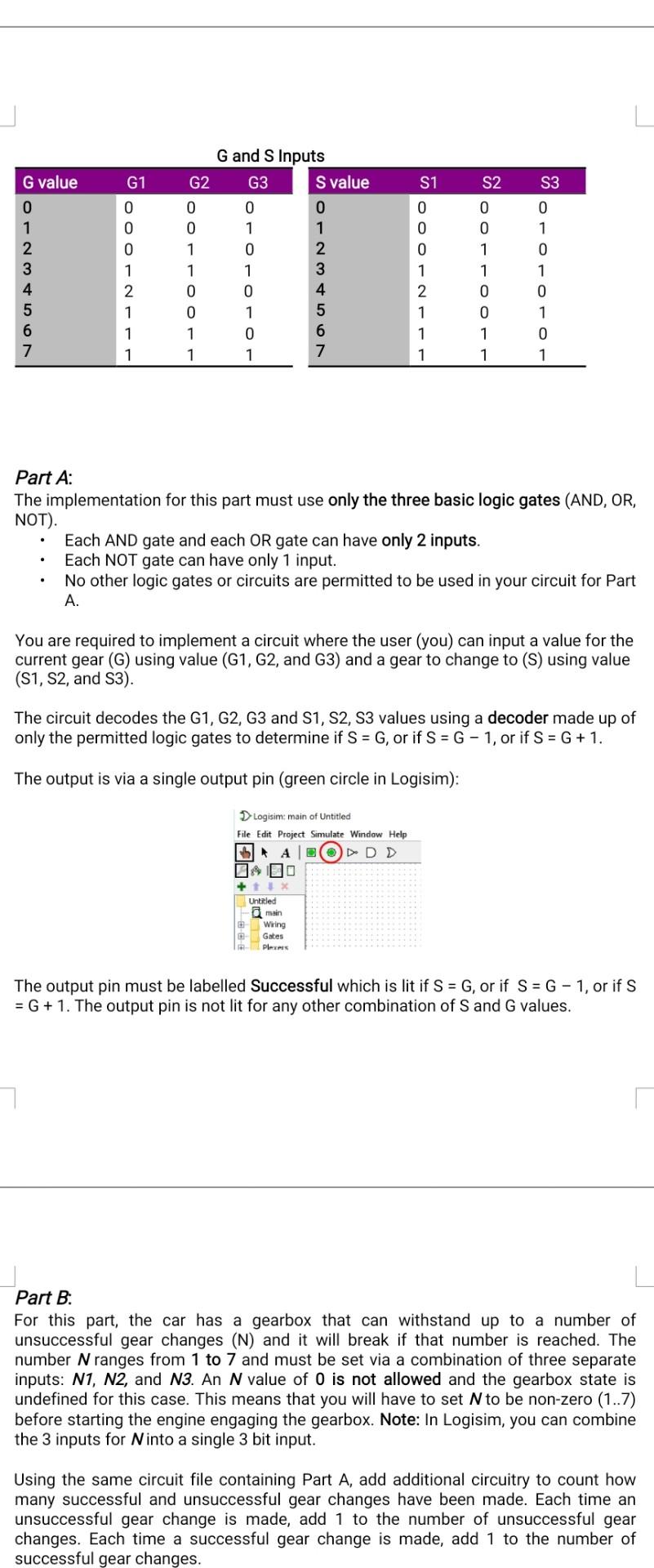
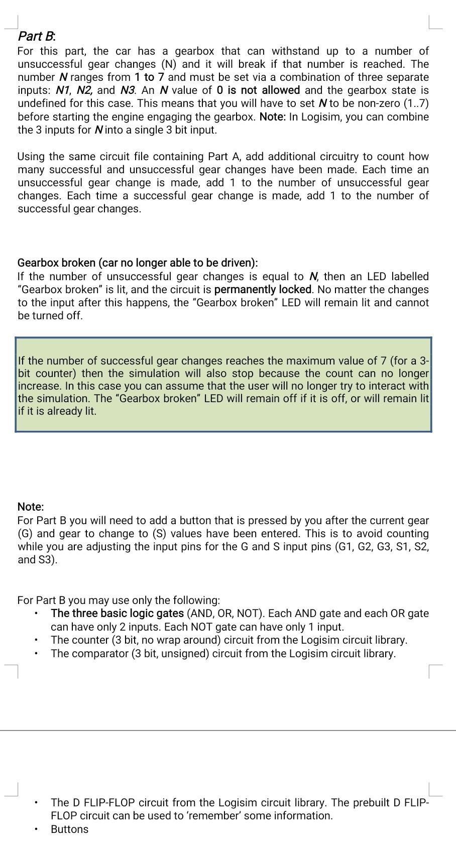
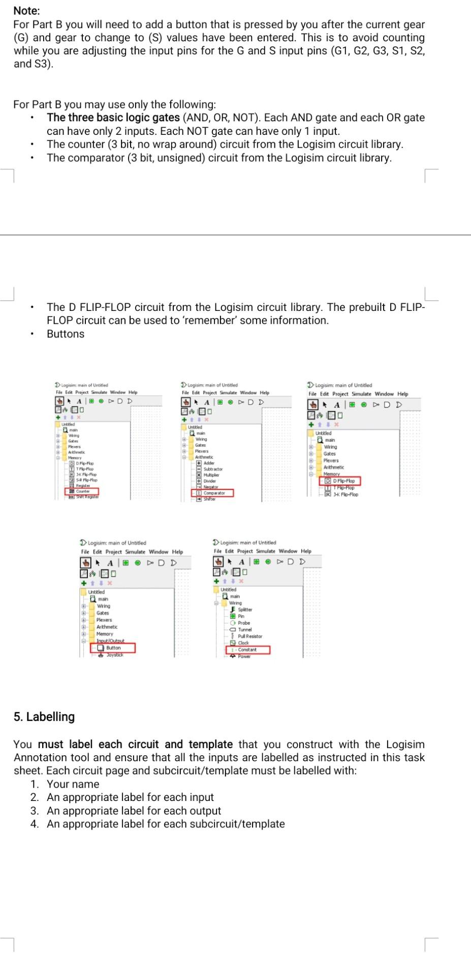
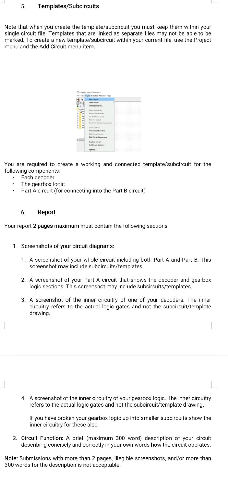
2. Software Requirement In this task, you will be using the Logisim circuit drawing software to create a circuit for the problem specified in this task. You must use the Logisim simulator version 2.7.1 to create your circuits 4. Task Description For this task you are required to implement a simple simulation of a gearbox in a car. The gearbox has two inputs: Input 1 (G) represents the current gear (0-7). Input 2 (S) represents the gear that the driver wants to change to (0-7). The gear change is successful if S = G, or if S = G - 1, or if S = G + 1. Any other value for S outside of this range will result in an unsuccessful gear change. Example 1: The current gear (G) is 2 and the gear we want to change to (S) is 3. In this case the requirement S = 6 + 1 is met and the gear change is successful. Example 2: The current gear (G) is 2 and the gear we want to change to (S) is 4. In this case S is outside the allowed range and the gear change is unsuccessful. Example 3: The current gear (G) is 0 and the gear we want to change to (S) is 0. In this case the requirement S = G is met and the gear change is successful. Note: These are just a few examples. There are (many) more cases that result in successful or unsuccessful gear changes. Your circuit must correctly show a successful or unsuccessful gear change for each possible case. For this task, the current gear (G) will be represented by three inputs (3 bits). The three G inputs are named as G1, G2, and G3. The table below shows the assignment of bits to each G value for G1, G2, and G3. For this task, the gear that we want to change to (S) will be represented by three inputs (3 bits). The three S inputs are named as S1, S2, and S3. The table below shows the assignment of bits to each S value for S1, S2, and S3. G and S Inputs G2 G3 S value G1 S1 S2 S3 0 0 0 0 0 G value 0 1 2 3 4 0 1 2 0 0 1 1 0 0 1 0 1 0 0 1 2 3 4 0 0 1 2 0 1 1 0 1 0 1 0 G value G1 S1 S2 S3 OO 0 0 0 1 2 1 1 1 OOOO G and S Inputs G2 G3 S value 0 1 1 1 0 2 1 1 3 0 4 1 5 1 0 6 1 1 0 0 0 1 2 1 1 1 1 1 0 0 1 0 1 0 1 0 1 O O 4 5 6 7 1 1 Part A The implementation for this part must use only the three basic logic gates (AND, OR, NOT) Each AND gate and each OR gate can have only 2 inputs. Each NOT gate can have only 1 input. No other logic gates or circuits are permitted to be used in your circuit for Part A. . . You are required to implement a circuit where the user (you) can input a value for the current gear (G) using value (G1, G2, and G3) and a gear to change to (S) using value (S1, S2, and S3). The circuit decodes the G1, G2, G3 and S1, S2, S3 values using a decoder made up of only the permitted logic gates to determine if S = G, or if S = G-1, or if S = G+1. The output is via a single output pin (green circle in Logisim): Logisim: main of Untitled File Edit Project Simulate Window Help A D D + x Untitled main Wiring Gates Plexes The output pin must be labelled Successful which is lit if S = G, or if S = G-1, or if S - G+ 1. The output pin is not lit for any other combination of S and G values. Part B For this part, the car has a gearbox that can withstand up to a number of unsuccessful gear changes (N) and it will break if that number is reached. The number N ranges from 1 to 7 and must be set via a combination of three separate inputs: N1, N2, and N3. An N value of 0 is not allowed and the gearbox state is undefined for this case. This means that you will have to set N to be non-zero (1..7) before starting the engine engaging the gearbox. Note: In Logisim, you can combine the 3 inputs for Ninto a single 3 bit input. Using the same circuit file containing Part A, add additional circuitry to count how many successful and unsuccessful gear changes have been made. Each time an unsuccessful gear change is made, add 1 to the number of unsuccessful gear changes. Each time a successful gear change is made, add 1 to the number of successful gear changes. Part B. For this part, the car has a gearbox that can withstand up to a number of unsuccessful gear changes (N) and it will break if that number is reached. The number N ranges from 1 to 7 and must be set via a combination of three separate inputs: N1, N2, and N3. An N value of 0 is not allowed and the gearbox state is undefined for this case. This means that you will have to set N to be non-zero (1..7) before starting the engine engaging the gearbox. Note: In Logisim, you can combine the 3 inputs for Ninto a single 3 bit input. Using the same circuit file containing Part A, add additional circuitry to count how many successful and unsuccessful gear changes have been made. Each time an unsuccessful gear change is made, add 1 to the number of unsuccessful gear changes. Each time a successful gear change is made, add 1 to the number of successful gear changes. Gearbox broken (car no longer able to be driven): If the number of unsuccessful gear changes is equal to N, then an LED labelled "Gearbox broken is lit, and the circuit is permanently locked. No matter the changes to the input after this happens, the "Gearbox broken LED will remain lit and cannot be turned off. If the number of successful gear changes reaches the maximum value of 7 (for a 3- bit counter) then the simulation will also stop because the count can no longer increase. In this case you can assume that the user will no longer try to interact with the simulation. The "Gearbox broken" LED will remain off if it is off, or will remain lit if it is already lit. Note: For Part B you will need to add a button that is pressed by you after the current gear (G) and gear to change to (S) values have been entered. This is to avoid counting while you are adjusting the input pins for the G and S input pins (G1, G2, G3, S1, S2, and S3). For Part B you may use only the following: The three basic logic gates (AND, OR, NOT). Each AND gate and each OR gate can have only 2 inputs. Each NOT gate can have only 1 input. The counter (3 bit, no wrap around) circuit from the Logisim circuit library. The comparator (3 bit, unsigned) circuit from the Logisim circuit library. The D FLIP-FLOP circuit from the Logisim circuit library. The prebuilt D FLIP- FLOP circuit can be used to 'remember' some information. Buttons Note: For Part B you will need to add a button that is pressed by you after the current gear (G) and gear to change to (S) values have been entered. This is to avoid counting while you are adjusting the input pins for the G and S input pins (G1, G2, G3, S1, S2, and S3) For Part B you may use only the following: The three basic logic gates (AND, OR, NOT). Each AND gate and each OR gate can have only 2 inputs. Each NOT gate can have only 1 input. The counter (3 bit, no wrap around) circuit from the Logisim circuit library. The comparator (3 bit, unsigned) circuit from the Logisim circuit library. The D FLIP-FLOP circuit from the Logisim circuit library. The prebuilt D FLIP- FLOP circuit can be used to 'remember' some information. Buttons Logisim main of Untitled File Edit Project Simulate Window Help Logisime main of Untitled File Edit Project Simulate Window Help Logisim: main of Untitled File Edit Project Simulate Window Help hl A | D P United Wing + Urted man wing Gates Plesers Arithmet + Adda Subtractor x Multiple Unttled main Wiring Gates Pleas Art Memory Dipe 1 Top Fles Sip-Flo Register 2 Counter Regee Plexes Divider Arithmetic Memory D Dip-Flop Up-Flop TK 14 Flo-Flop E Negato a Comparator Shiter Logisime main of Untitled File Edit Project Simulate Window Help hl A DDD +tX Untitled Logisime main of Untitled File Edit Project Simulate Window Help E DD DO + Untitled man Wiring Splitter Pin Probe Tunnel PA Resistor Clock 1. Constant Power + Wiring Gates Plexers Arithmetic Memory Institut Button oystic + 5. Labelling You must label each circuit and template that you construct with the Logisim Annotation tool and ensure that all the inputs are labelled as instructed in this task sheet. Each circuit page and subcircuit/template must be labelled with: 1. Your name 2. An appropriate label for each input 3. An appropriate label for each output 4. An appropriate label for each subcircuit/template 5. Templates/Subcircuits Note that when you create the template/subcircuit you must keep them within your single circuit file. Templates that are linked as separate files may not be able to be marked. To create a new template/subcircuit within your current file, use the Project menu and the Add Circuit menu item. 16 Es You are required to create a working and connected template/subcircuit for the following components: Each decoder The gearbox logic Part A circuit (for connecting into the Part B circuit) 6. Report Your report 2 pages maximum must contain the following sections: 1. Screenshots of your circuit diagrams: 1. A screenshot of your whole circuit including both Part A and Part B. This screenshot may include subcircuits/templates. 2. A screenshot of your Part A circuit that shows the decoder and gearbox logic sections. This screenshot may include subcircuits/templates. 3. A screenshot of the inner circuitry of one of your decoders. The inner circuitry refers to the actual logic gates and not the subcircuit/template drawing. 4. A screenshot of the inner circuitry of your gearbox logic. The inner circuitry refers to the actual logic gates and not the subcircuit/template drawing. If you have broken your gearbox logic up into smaller subcircuits show the inner circuitry for these also. 2. Circuit Function: A brief (maximum 300 word) description of your circuit describing concisely and correctly in your own words how the circuit operates. Note: Submissions with more than 2 pages, illegible screenshots, and/or more than 300 words for the description is not acceptable. 2. Software Requirement In this task, you will be using the Logisim circuit drawing software to create a circuit for the problem specified in this task. You must use the Logisim simulator version 2.7.1 to create your circuits 4. Task Description For this task you are required to implement a simple simulation of a gearbox in a car. The gearbox has two inputs: Input 1 (G) represents the current gear (0-7). Input 2 (S) represents the gear that the driver wants to change to (0-7). The gear change is successful if S = G, or if S = G - 1, or if S = G + 1. Any other value for S outside of this range will result in an unsuccessful gear change. Example 1: The current gear (G) is 2 and the gear we want to change to (S) is 3. In this case the requirement S = 6 + 1 is met and the gear change is successful. Example 2: The current gear (G) is 2 and the gear we want to change to (S) is 4. In this case S is outside the allowed range and the gear change is unsuccessful. Example 3: The current gear (G) is 0 and the gear we want to change to (S) is 0. In this case the requirement S = G is met and the gear change is successful. Note: These are just a few examples. There are (many) more cases that result in successful or unsuccessful gear changes. Your circuit must correctly show a successful or unsuccessful gear change for each possible case. For this task, the current gear (G) will be represented by three inputs (3 bits). The three G inputs are named as G1, G2, and G3. The table below shows the assignment of bits to each G value for G1, G2, and G3. For this task, the gear that we want to change to (S) will be represented by three inputs (3 bits). The three S inputs are named as S1, S2, and S3. The table below shows the assignment of bits to each S value for S1, S2, and S3. G and S Inputs G2 G3 S value G1 S1 S2 S3 0 0 0 0 0 G value 0 1 2 3 4 0 1 2 0 0 1 1 0 0 1 0 1 0 0 1 2 3 4 0 0 1 2 0 1 1 0 1 0 1 0 G value G1 S1 S2 S3 OO 0 0 0 1 2 1 1 1 OOOO G and S Inputs G2 G3 S value 0 1 1 1 0 2 1 1 3 0 4 1 5 1 0 6 1 1 0 0 0 1 2 1 1 1 1 1 0 0 1 0 1 0 1 0 1 O O 4 5 6 7 1 1 Part A The implementation for this part must use only the three basic logic gates (AND, OR, NOT) Each AND gate and each OR gate can have only 2 inputs. Each NOT gate can have only 1 input. No other logic gates or circuits are permitted to be used in your circuit for Part A. . . You are required to implement a circuit where the user (you) can input a value for the current gear (G) using value (G1, G2, and G3) and a gear to change to (S) using value (S1, S2, and S3). The circuit decodes the G1, G2, G3 and S1, S2, S3 values using a decoder made up of only the permitted logic gates to determine if S = G, or if S = G-1, or if S = G+1. The output is via a single output pin (green circle in Logisim): Logisim: main of Untitled File Edit Project Simulate Window Help A D D + x Untitled main Wiring Gates Plexes The output pin must be labelled Successful which is lit if S = G, or if S = G-1, or if S - G+ 1. The output pin is not lit for any other combination of S and G values. Part B For this part, the car has a gearbox that can withstand up to a number of unsuccessful gear changes (N) and it will break if that number is reached. The number N ranges from 1 to 7 and must be set via a combination of three separate inputs: N1, N2, and N3. An N value of 0 is not allowed and the gearbox state is undefined for this case. This means that you will have to set N to be non-zero (1..7) before starting the engine engaging the gearbox. Note: In Logisim, you can combine the 3 inputs for Ninto a single 3 bit input. Using the same circuit file containing Part A, add additional circuitry to count how many successful and unsuccessful gear changes have been made. Each time an unsuccessful gear change is made, add 1 to the number of unsuccessful gear changes. Each time a successful gear change is made, add 1 to the number of successful gear changes. Part B. For this part, the car has a gearbox that can withstand up to a number of unsuccessful gear changes (N) and it will break if that number is reached. The number N ranges from 1 to 7 and must be set via a combination of three separate inputs: N1, N2, and N3. An N value of 0 is not allowed and the gearbox state is undefined for this case. This means that you will have to set N to be non-zero (1..7) before starting the engine engaging the gearbox. Note: In Logisim, you can combine the 3 inputs for Ninto a single 3 bit input. Using the same circuit file containing Part A, add additional circuitry to count how many successful and unsuccessful gear changes have been made. Each time an unsuccessful gear change is made, add 1 to the number of unsuccessful gear changes. Each time a successful gear change is made, add 1 to the number of successful gear changes. Gearbox broken (car no longer able to be driven): If the number of unsuccessful gear changes is equal to N, then an LED labelled "Gearbox broken is lit, and the circuit is permanently locked. No matter the changes to the input after this happens, the "Gearbox broken LED will remain lit and cannot be turned off. If the number of successful gear changes reaches the maximum value of 7 (for a 3- bit counter) then the simulation will also stop because the count can no longer increase. In this case you can assume that the user will no longer try to interact with the simulation. The "Gearbox broken" LED will remain off if it is off, or will remain lit if it is already lit. Note: For Part B you will need to add a button that is pressed by you after the current gear (G) and gear to change to (S) values have been entered. This is to avoid counting while you are adjusting the input pins for the G and S input pins (G1, G2, G3, S1, S2, and S3). For Part B you may use only the following: The three basic logic gates (AND, OR, NOT). Each AND gate and each OR gate can have only 2 inputs. Each NOT gate can have only 1 input. The counter (3 bit, no wrap around) circuit from the Logisim circuit library. The comparator (3 bit, unsigned) circuit from the Logisim circuit library. The D FLIP-FLOP circuit from the Logisim circuit library. The prebuilt D FLIP- FLOP circuit can be used to 'remember' some information. Buttons Note: For Part B you will need to add a button that is pressed by you after the current gear (G) and gear to change to (S) values have been entered. This is to avoid counting while you are adjusting the input pins for the G and S input pins (G1, G2, G3, S1, S2, and S3) For Part B you may use only the following: The three basic logic gates (AND, OR, NOT). Each AND gate and each OR gate can have only 2 inputs. Each NOT gate can have only 1 input. The counter (3 bit, no wrap around) circuit from the Logisim circuit library. The comparator (3 bit, unsigned) circuit from the Logisim circuit library. The D FLIP-FLOP circuit from the Logisim circuit library. The prebuilt D FLIP- FLOP circuit can be used to 'remember' some information. Buttons Logisim main of Untitled File Edit Project Simulate Window Help Logisime main of Untitled File Edit Project Simulate Window Help Logisim: main of Untitled File Edit Project Simulate Window Help hl A | D P United Wing + Urted man wing Gates Plesers Arithmet + Adda Subtractor x Multiple Unttled main Wiring Gates Pleas Art Memory Dipe 1 Top Fles Sip-Flo Register 2 Counter Regee Plexes Divider Arithmetic Memory D Dip-Flop Up-Flop TK 14 Flo-Flop E Negato a Comparator Shiter Logisime main of Untitled File Edit Project Simulate Window Help hl A DDD +tX Untitled Logisime main of Untitled File Edit Project Simulate Window Help E DD DO + Untitled man Wiring Splitter Pin Probe Tunnel PA Resistor Clock 1. Constant Power + Wiring Gates Plexers Arithmetic Memory Institut Button oystic + 5. Labelling You must label each circuit and template that you construct with the Logisim Annotation tool and ensure that all the inputs are labelled as instructed in this task sheet. Each circuit page and subcircuit/template must be labelled with: 1. Your name 2. An appropriate label for each input 3. An appropriate label for each output 4. An appropriate label for each subcircuit/template 5. Templates/Subcircuits Note that when you create the template/subcircuit you must keep them within your single circuit file. Templates that are linked as separate files may not be able to be marked. To create a new template/subcircuit within your current file, use the Project menu and the Add Circuit menu item. 16 Es You are required to create a working and connected template/subcircuit for the following components: Each decoder The gearbox logic Part A circuit (for connecting into the Part B circuit) 6. Report Your report 2 pages maximum must contain the following sections: 1. Screenshots of your circuit diagrams: 1. A screenshot of your whole circuit including both Part A and Part B. This screenshot may include subcircuits/templates. 2. A screenshot of your Part A circuit that shows the decoder and gearbox logic sections. This screenshot may include subcircuits/templates. 3. A screenshot of the inner circuitry of one of your decoders. The inner circuitry refers to the actual logic gates and not the subcircuit/template drawing. 4. A screenshot of the inner circuitry of your gearbox logic. The inner circuitry refers to the actual logic gates and not the subcircuit/template drawing. If you have broken your gearbox logic up into smaller subcircuits show the inner circuitry for these also. 2. Circuit Function: A brief (maximum 300 word) description of your circuit describing concisely and correctly in your own words how the circuit operates. Note: Submissions with more than 2 pages, illegible screenshots, and/or more than 300 words for the description is not acceptable
Step by Step Solution
There are 3 Steps involved in it
Step: 1

Get Instant Access to Expert-Tailored Solutions
See step-by-step solutions with expert insights and AI powered tools for academic success
Step: 2

Step: 3
Ace Your Homework with AI
Get the answers you need in no time with our AI-driven, step-by-step assistance
Get Started
Machine Learning And Knowledge Discovery In Databases European Conference Ecml Pkdd 2015 Porto Portugal September 7 11 2015 Proceedings Part 2 Lnai 9285
Authors: Annalisa Appice ,Pedro Pereira Rodrigues ,Vitor Santos Costa ,Joao Gama ,Alipio Jorge ,Carlos Soares
1st Edition