

Answered step by step
Verified Expert Solution
Question
1 Approved Answer
20 10 Maximum total head 18 Taal dynamic bead, m 17 Minimum total head 15 3.000 6.000 12.000 FIGURE 3-16 System total head curves. Flow
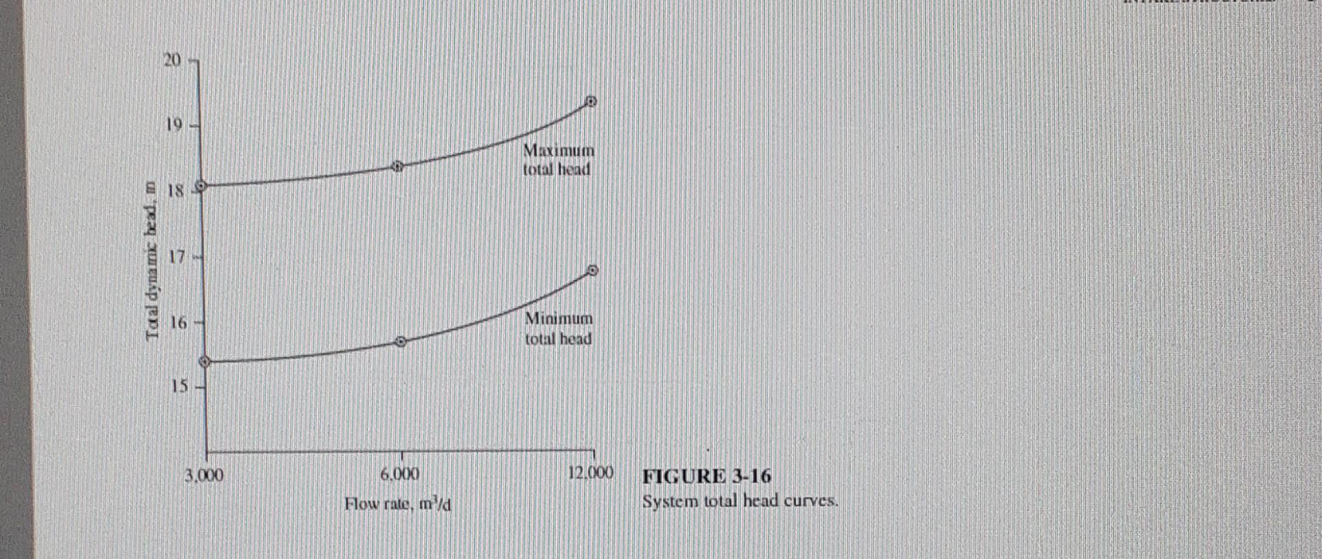
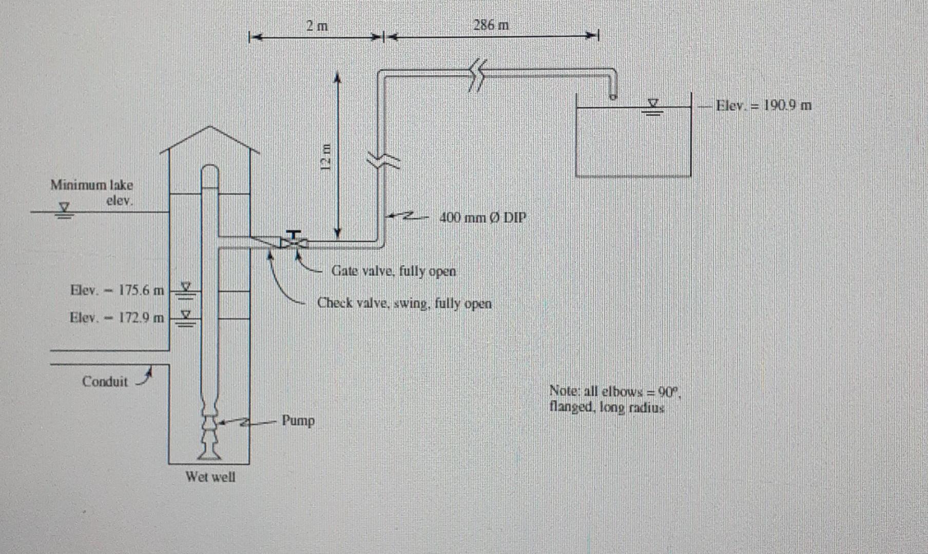
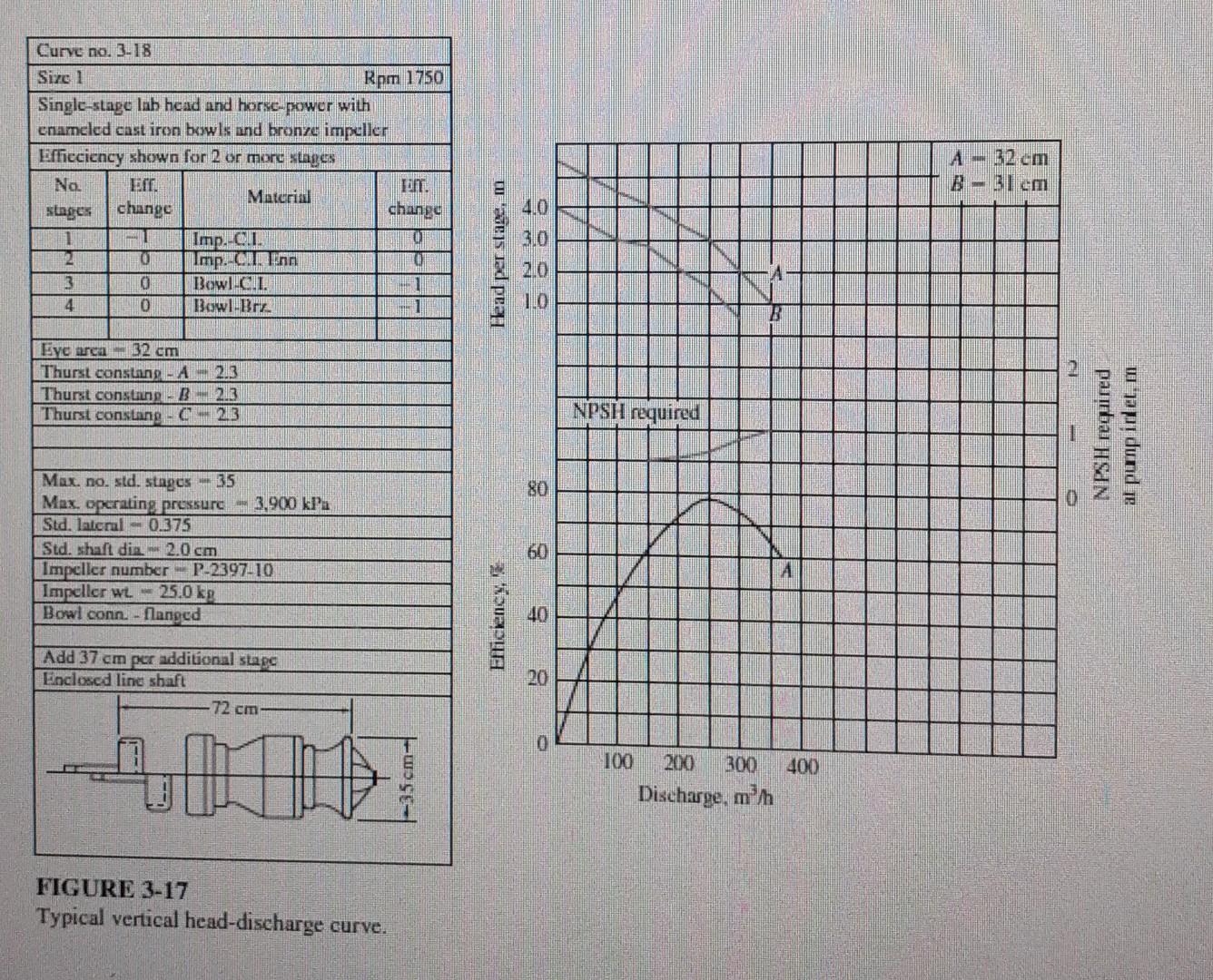
20 10 Maximum total head 18 Taal dynamic bead, m 17 Minimum total head 15 3.000 6.000 12.000 FIGURE 3-16 System total head curves. Flow rate, ma 2 m 286 m Elev. = 190.9 m Minimum lake elev. 400 mm DIP Gate valve, fully open Elev. 175.6 m Elev. - 172.9 m Check valve, swing, fully open Conduit Note: all elbows = 90. flanged, long radius Pump Wet well Curve no. 3.18 Size 1 Rpm 1750 Single-stage lab head and horse-power with enameled cast iron bowls and bronze impeller Efficciency shown for 2 or more stages Na. TOT. Material stages change change 1 ET Imp.-c... 02 2 0 Imp. cum Inn 3 0 Bowl G.T. 4 0 BowI-BIELE 1 A 32 cm B = 31cm Head per stage, m 4.0 3.0 2.0 A 1.0 2 Eye area 32 cm Thurst constang A213 Thurst constang - B 213 Thurst constang - C - 2.3 NPSH required 1 NPSH required al punpillet, m 80 Max. no. std. stages - 35 Max. operating pressure 3.900 kPa Std. lateral - 0.375 Std. shaft din. 2.0 cm Impeller number - P-2397-10 Impeller wl. - 25.0 kg Bowl conn. - flanged 60 A 40 Elficiency, Add 37 cm per additional stape Enclosed line shaft -72 cm 20 0 400 100 200 300 Discharge, men FIGURE 3-17 Typical vertical head-discharge curve. Chemical Engineering Using the pump head-discharge curve shown in Figure 3-17 for the system head curve shown in Figure 3-16, specify the following at the average flow rate: (1) BEP, (2) number of stages, (3) efficiency at BEP
Step by Step Solution
There are 3 Steps involved in it
Step: 1

Get Instant Access to Expert-Tailored Solutions
See step-by-step solutions with expert insights and AI powered tools for academic success
Step: 2

Step: 3
Ace Your Homework with AI
Get the answers you need in no time with our AI-driven, step-by-step assistance
Get Started
Separation process principles
Authors: J. D. Seader
2nd Edition
471464805, 978-0471464808