Answered step by step
Verified Expert Solution
Question
1 Approved Answer
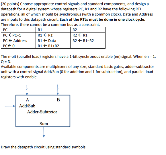
(20 points) Choose appropriate control signals and standard components, and design a datapath for a digital system whose registers PC, R1 and R2 have the

(20 points) Choose appropriate control signals and standard components, and design a datapath for a digital system whose registers PC, R1 and R2 have the following RTL operations, all of which should be synchronous (with a common clock). Data and Address are inputs to this datapath circuit. Each of the RTLs must be done in one clock cycle. Therefore, there cannot be a common bus as a constraint. PC R1 R2 PC PC+1 R1 R1' R2 R1 PC Address R1 Data R2 + R1-R2 PCE O R1 R1+R2 The n-bit (parallel load) registers have a 1-bit synchronous enable (en) signal. When en = 1, Q = D. Available components are multiplexers of any size, standard basic gates, adder-subtractor unit with a control signal Add/Sub (0 for addition and 1 for subtraction), and parallel-load registers with enable. A B Add/Sub Adder-Subtrctor Sum Draw the datapath circuit using standard symbols
Step by Step Solution
There are 3 Steps involved in it
Step: 1

Get Instant Access to Expert-Tailored Solutions
See step-by-step solutions with expert insights and AI powered tools for academic success
Step: 2

Step: 3

Ace Your Homework with AI
Get the answers you need in no time with our AI-driven, step-by-step assistance
Get Started


