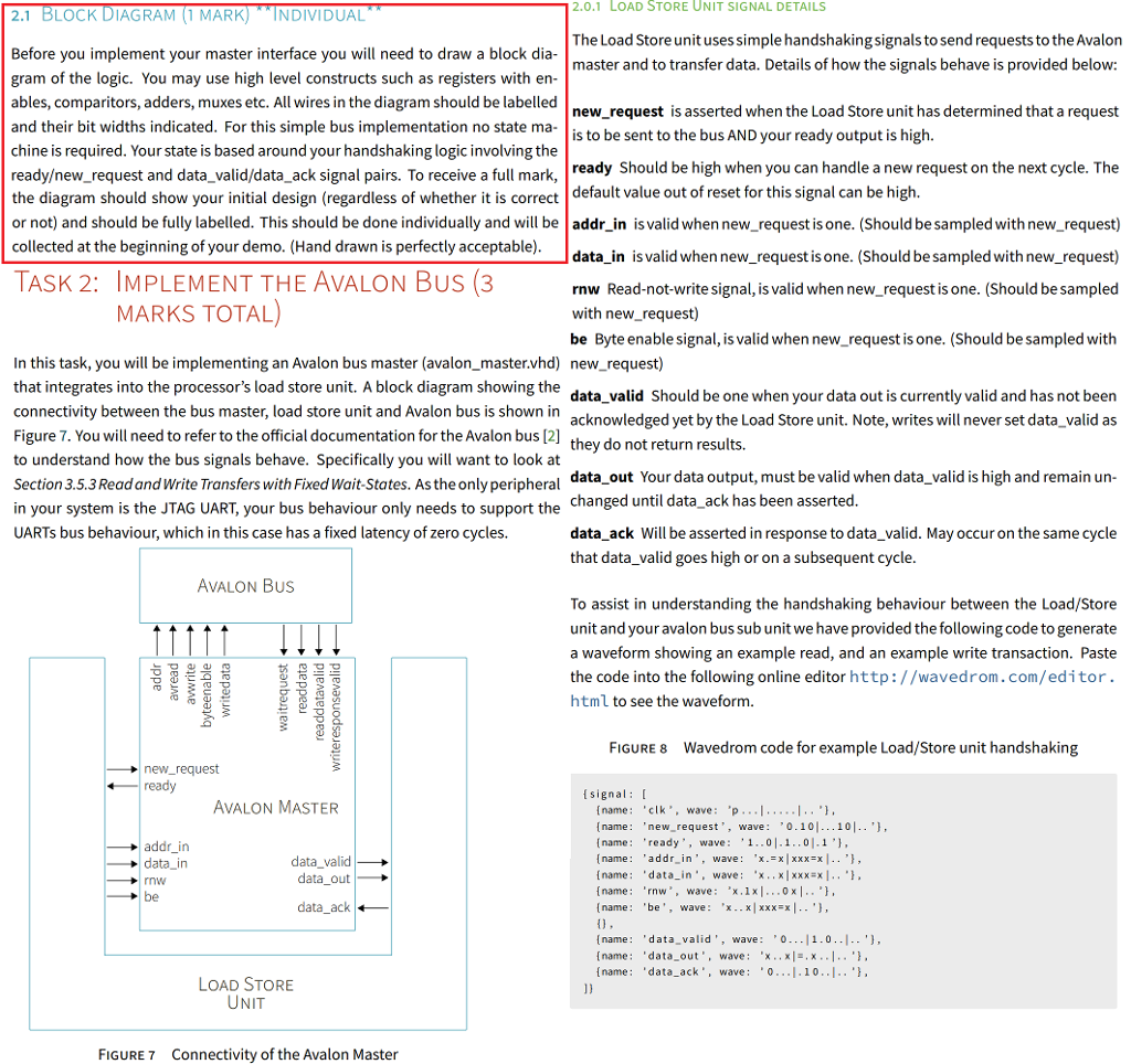
2.0.1 LOAD STORE UNIT SIGNAL DETAILS 2.1 BLOCK DIAGRAM (1 MARK)INDIVIDUAL The Load Store unit uses simple handshakingsignals to send requests to the Avalon master and to transfer data. Details of how the signals behave is provided below: Before you implement your master interface you will need to draw a block dia gram of the logic. You may use high level constructs such as registers with en- ables, comparitors, adders, muxes etc. All wires in the diagram should be labelled and their bit widths indicated. For this simple bus implementation no state ma chine is required. Your state is based around your handshaking logic involving the readyew_request and data_valid/data_ack signal pairs. To receive a full mark, the diagram should show your initial design (regardless of whether it is correct default value out of reset for this signal can be high or not) and should be fully labelled. This should be done individualy and il be addr_in is valid when new_request is one. (Should be sampled with new_request) collected at the beginning of your demo. (Hand drawn is perfectly acceptable) - | new_request is asserted when the Load Store unit has determined that a request is to be sent to the bus AND your ready output is high. ready Should be high when you can handle a new request on the next cycle. The data_in is valid when new_request is one. (Should be sampled with new_request) rnw Read-not-write signal, is valid when new_request is one. (Should be sampled with new_request) be Byte enable signal, is valid when new_request is one. (Should be sampled with TASK 2: IMPLEMENT THE AVALON BuS (3 MARKS TOTAL) In this task, you will be implementing an Avalon bus master (avalon_master.vhd) new_request) that integrates into the processor's load store unit. A block diagram showing the connectivity between the bus master, load store unit and Avalon bus is shown in Figure 7. You will need to refer to the official documentation for the Avalon bus [2] to understand how the bus signals behave. Specifically you will want to look at Section 3.5.3 Read and Write Transfers with Fixed Wait-States. As the only peripheral in your system is the JTAG UART, your bus behaviour only needs to support the UARTs bus behaviour, which in this case has a fixed latency of zero cycles. data_valid Should be one when your data out is currently valid and has not beern acknowledged yet by the Load Store unit. Note, writes will never set data_valid as they do not return results. data_out Your data output, must be valid when data_valid is high and remain un changed until data_ack has been asserted data ack Will be asserted in response to data_valid. May occur on the same cycle that data_valid goes high or on a subsequent cycle AVALON Bus To assist in understanding the handshaking behaviour between the Load/Store unit and your avalon bus sub unit we have provided the following code to generate a waveform showing an example read, and an example write transaction. Paste the code into the following online editor http://wavedrom.com/editor. html to see the waveform. FIGURE 8 Wavedrom code for example Load/Store unit handshaking new request ready signal [ AVALON MASTER addr in data_in nw be [name: clk",wave: p...1...I." name: 'new_request, wave: 0.10.. 10.. ', name 'ready', wa 1..0.1..0.1 ', name: 'addr in, wave: "x.-xxxxEx.', [name: "data in,wave: 'x.. x|xxxx. [name 'rnw, wave 'x.1x.0x', name be, wave: 'x..x xxxx .. '], data_valid data out data ack name data valid', wave: 0..1.0.. Iname: 'data_out,wave x.xx..' [name "data_ack', wave 1.10..I. LOAD STORE UNIT FIGURE7 Connectivity of the Avalon Master 2.0.1 LOAD STORE UNIT SIGNAL DETAILS 2.1 BLOCK DIAGRAM (1 MARK)INDIVIDUAL The Load Store unit uses simple handshakingsignals to send requests to the Avalon master and to transfer data. Details of how the signals behave is provided below: Before you implement your master interface you will need to draw a block dia gram of the logic. You may use high level constructs such as registers with en- ables, comparitors, adders, muxes etc. All wires in the diagram should be labelled and their bit widths indicated. For this simple bus implementation no state ma chine is required. Your state is based around your handshaking logic involving the readyew_request and data_valid/data_ack signal pairs. To receive a full mark, the diagram should show your initial design (regardless of whether it is correct default value out of reset for this signal can be high or not) and should be fully labelled. This should be done individualy and il be addr_in is valid when new_request is one. (Should be sampled with new_request) collected at the beginning of your demo. (Hand drawn is perfectly acceptable) - | new_request is asserted when the Load Store unit has determined that a request is to be sent to the bus AND your ready output is high. ready Should be high when you can handle a new request on the next cycle. The data_in is valid when new_request is one. (Should be sampled with new_request) rnw Read-not-write signal, is valid when new_request is one. (Should be sampled with new_request) be Byte enable signal, is valid when new_request is one. (Should be sampled with TASK 2: IMPLEMENT THE AVALON BuS (3 MARKS TOTAL) In this task, you will be implementing an Avalon bus master (avalon_master.vhd) new_request) that integrates into the processor's load store unit. A block diagram showing the connectivity between the bus master, load store unit and Avalon bus is shown in Figure 7. You will need to refer to the official documentation for the Avalon bus [2] to understand how the bus signals behave. Specifically you will want to look at Section 3.5.3 Read and Write Transfers with Fixed Wait-States. As the only peripheral in your system is the JTAG UART, your bus behaviour only needs to support the UARTs bus behaviour, which in this case has a fixed latency of zero cycles. data_valid Should be one when your data out is currently valid and has not beern acknowledged yet by the Load Store unit. Note, writes will never set data_valid as they do not return results. data_out Your data output, must be valid when data_valid is high and remain un changed until data_ack has been asserted data ack Will be asserted in response to data_valid. May occur on the same cycle that data_valid goes high or on a subsequent cycle AVALON Bus To assist in understanding the handshaking behaviour between the Load/Store unit and your avalon bus sub unit we have provided the following code to generate a waveform showing an example read, and an example write transaction. Paste the code into the following online editor http://wavedrom.com/editor. html to see the waveform. FIGURE 8 Wavedrom code for example Load/Store unit handshaking new request ready signal [ AVALON MASTER addr in data_in nw be [name: clk",wave: p...1...I." name: 'new_request, wave: 0.10.. 10.. ', name 'ready', wa 1..0.1..0.1 ', name: 'addr in, wave: "x.-xxxxEx.', [name: "data in,wave: 'x.. x|xxxx. [name 'rnw, wave 'x.1x.0x', name be, wave: 'x..x xxxx .. '], data_valid data out data ack name data valid', wave: 0..1.0.. Iname: 'data_out,wave x.xx..' [name "data_ack', wave 1.10..I. LOAD STORE UNIT FIGURE7 Connectivity of the Avalon Master