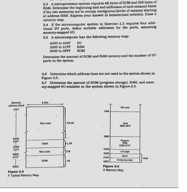
2.3 A microprocessor system requires 4K bytes of ROM and 256 bytes of RAM. Determine the beginning and end addresses of each memory block if the two memories are to occupy contiguous blocks of memory starting at address 0000. Express your answer in hexadecimal notation. Draw a memory map. 2.4 If the microcomputer system in Exercise 2.3 requtres four addi- tional Vo ports, define suitable addresses for the ports, assuming memory-mapped Vo. 2.5 A microcomputer has the following memory map: 4000 to 400F VO 2000 to 21FF RAM 0000 to OFFF ROM Determine the amount of ROM and RAM memory and the number of VO ports in the system. 2.6 Determine which address lines are not used in the system shown in Figure 2.5. 2.7 Determine the amount of ROM (program storage), RAM, and mem- ory-mapped VO avallable in the system shown in Figure 2.6. 8 bits Memory address (hex) FFFF Not used 1000 Not used -54.5K RAM 0800-OFFF 2600 25FF RAM 1.5K 2000 1FFF 0800 07FF Not used 6K Vop 0800 Program ROM 0300-07FF 0300 0200 0100 Stack 0000 Temporary data Figure 2.6 A Memory Map . RAM ROM 2K 0000 Figure 2.5 A Typical Memory Map. 2.3 A microprocessor system requires 4K bytes of ROM and 256 bytes of RAM. Determine the beginning and end addresses of each memory block if the two memories are to occupy contiguous blocks of memory starting at address 0000. Express your answer in hexadecimal notation. Draw a memory map. 2.4 If the microcomputer system in Exercise 2.3 requtres four addi- tional Vo ports, define suitable addresses for the ports, assuming memory-mapped Vo. 2.5 A microcomputer has the following memory map: 4000 to 400F VO 2000 to 21FF RAM 0000 to OFFF ROM Determine the amount of ROM and RAM memory and the number of VO ports in the system. 2.6 Determine which address lines are not used in the system shown in Figure 2.5. 2.7 Determine the amount of ROM (program storage), RAM, and mem- ory-mapped VO avallable in the system shown in Figure 2.6. 8 bits Memory address (hex) FFFF Not used 1000 Not used -54.5K RAM 0800-OFFF 2600 25FF RAM 1.5K 2000 1FFF 0800 07FF Not used 6K Vop 0800 Program ROM 0300-07FF 0300 0200 0100 Stack 0000 Temporary data Figure 2.6 A Memory Map . RAM ROM 2K 0000 Figure 2.5 A Typical Memory Map


