Answered step by step
Verified Expert Solution
Question
1 Approved Answer
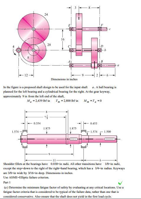
24 20 20 16 D b C B a Dimensions in inches In the figure is a proposed shaft design to be used for


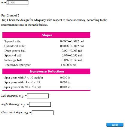
24 20 20 16 D b C B a Dimensions in inches In the figure is a proposed shaft design to be used for the input shaft a. A ball bearing is planned for the left bearing and a cylindrical bearing for the right. At the gear keyway. approximately 9 in from the left end of the shaft, Ma -2,439 lbf-in T = 2,800 lbf-in Mm-Ta=0 71 0.354 0.453 1.875 1.875 1.574 1.574 1.500 6 Shoulder fillets at the bearings have 0.030-in radii. All other transitions have 1/8-in radii, except the step-down to the right of the right-hand bearing, which has a 1/4-in radius. Keyways are 3/8-in wide by 3/16-in deep. Dimensions in inches. Use ASME-Elliptic failure criterion. Part 1 (a) Determine the minimum fatigue factor of safety by evaluating at any critical locations. Use a fatigue factor criteria that is considered to be typical of the failure data, rather than one that is considered conservative. Also ensure that the shaft does not yield in the first load cycle. 2.44 Part 2 out of 2 (b) Check the design for adequacy with respect to slope adequacy, according to the recommendations in the table below. Slopes Tapered roller 0.0005-0.0012 rad Cylindrical roller 0.0008-0.0012 rad Deep-groove ball 0.001-0.003 rad Spherical ball 0.026-0.052 rad Self-align ball 0.026-0.052 rad Uncrowned spur gear < 0.0005 rad Transverse Deflections Spur gears with P < 10 teeth/in 0.010 in Spur gears with 11 P < 19 0.005 in Spur gears with 20 < P < 50 0.003 in Left Bearing: nfs Right Bearing: nfs Gear mesh slope: nfs next
Step by Step Solution
There are 3 Steps involved in it
Step: 1

Get Instant Access to Expert-Tailored Solutions
See step-by-step solutions with expert insights and AI powered tools for academic success
Step: 2

Step: 3

Ace Your Homework with AI
Get the answers you need in no time with our AI-driven, step-by-step assistance
Get Started


