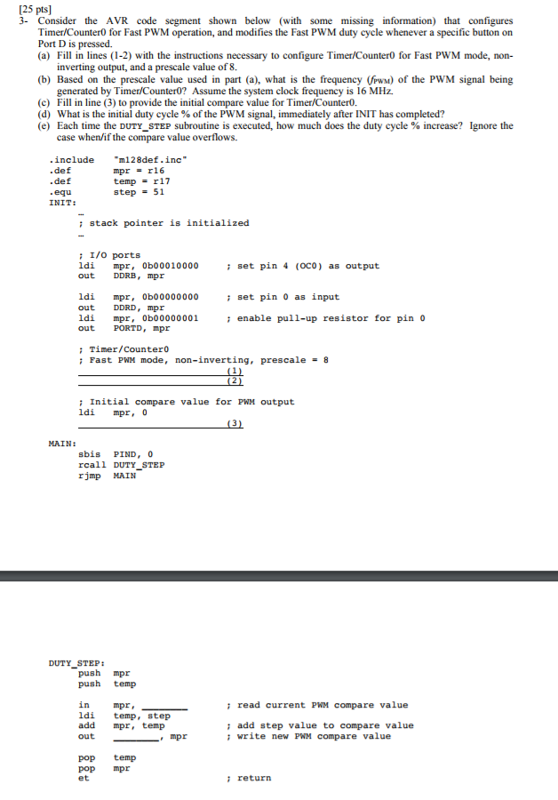
25 pts] 3- Consider the AVR code segment shown below (with some missing information) that configures Timer/Counter0 for Fast PWM operation, and modifies the Fast PWM duty cycle whenever a specific button on Port D is pressed. (a) ill in lines (1-2) with the instructions necessary to configure Timer/Counter0 for Fast PWM mode, non- inverting output, and a prescale value of 8. (b) Based on the prescale value used in part (a), what is the frequency (Pw) of the PWM signal being generated by Timer/Counter0? Assume the system clock frequency is 16 MHz. (c) Fill in line (3) to provide the initial compare value for Timer/Counter. (d) What is the initial duty cycle % of the PWM signal, immediately after INIT has completed? (e) Each time the DUTY STEP subroutine is executed, how much does the duty cycle % increase? Ignore the case when/if the compare value overflows. include 128def.inc" def def equ mpr = r16 temp = r17 step = 51 INIT: stack pointer is initialized : I/o ports ldi mpr, 0b00010000 out DDRB, mpr set pin 4 (oco) as output i set pin 0 as input i enable pull-up resistor for pin o ldi mpr, 0b00000000 out DDRD, mpr ldi mpr, 0b00000001 out PORTD, mpr Timer/Counter0 ; Fast PWM mode, non-inverting, prescale = 8 Initial compare value for PWM output ldi mpr, 0 MAIN: sbis PIND,0 rcall DUTY STEP rjmp MAIN DUTY STEP: push mpr push temp i read current PWM compare value in ldi temp, step add mpr, temp out mpr, i add step value to compare value mpr write new PWM compare value pop temp pop mpr et i return 25 pts] 3- Consider the AVR code segment shown below (with some missing information) that configures Timer/Counter0 for Fast PWM operation, and modifies the Fast PWM duty cycle whenever a specific button on Port D is pressed. (a) ill in lines (1-2) with the instructions necessary to configure Timer/Counter0 for Fast PWM mode, non- inverting output, and a prescale value of 8. (b) Based on the prescale value used in part (a), what is the frequency (Pw) of the PWM signal being generated by Timer/Counter0? Assume the system clock frequency is 16 MHz. (c) Fill in line (3) to provide the initial compare value for Timer/Counter. (d) What is the initial duty cycle % of the PWM signal, immediately after INIT has completed? (e) Each time the DUTY STEP subroutine is executed, how much does the duty cycle % increase? Ignore the case when/if the compare value overflows. include 128def.inc" def def equ mpr = r16 temp = r17 step = 51 INIT: stack pointer is initialized : I/o ports ldi mpr, 0b00010000 out DDRB, mpr set pin 4 (oco) as output i set pin 0 as input i enable pull-up resistor for pin o ldi mpr, 0b00000000 out DDRD, mpr ldi mpr, 0b00000001 out PORTD, mpr Timer/Counter0 ; Fast PWM mode, non-inverting, prescale = 8 Initial compare value for PWM output ldi mpr, 0 MAIN: sbis PIND,0 rcall DUTY STEP rjmp MAIN DUTY STEP: push mpr push temp i read current PWM compare value in ldi temp, step add mpr, temp out mpr, i add step value to compare value mpr write new PWM compare value pop temp pop mpr et i return


