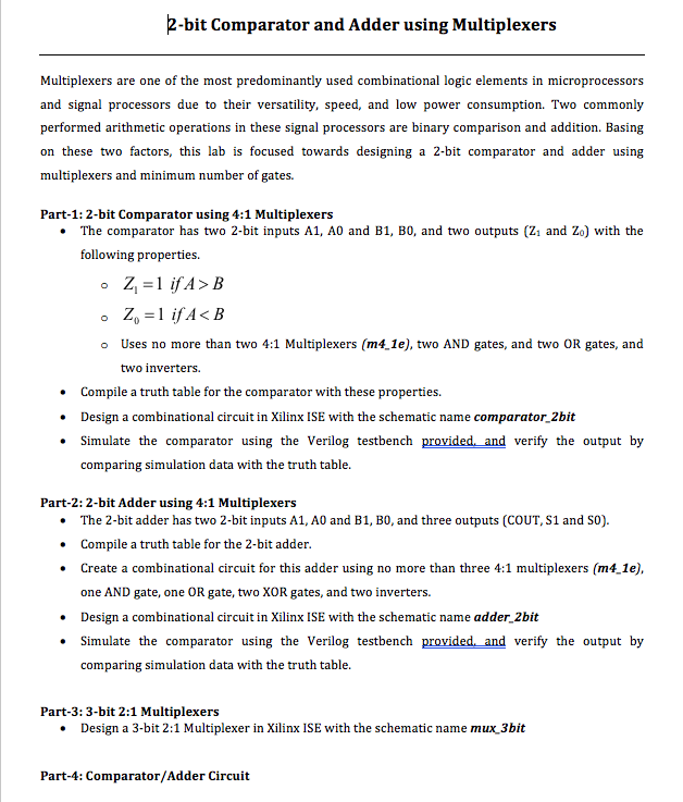
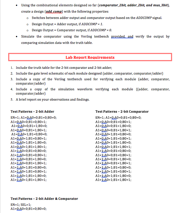
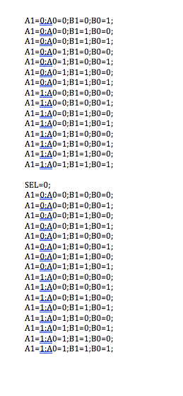
2-bit Comparator and Adder using Multiplexers Multiplexers are one of the most predominantly used combinational logic elements in microprocessors and signal processors due to their versatility, speed, and low power consumption. Two commonly performed arithmetic operations in these signal processors are binary comparison and addition. Basing on these two factors, this lab is focused towards designing a 2-bit comparator and adder using multiplexers and minimum number of gates. Part-1: 2-bit Comparator using 4:1 Multiplexers . The comparator has two 2-bit inputs A1, A0 and B1, B0, and two outputs (Z1 and Zo) with the following properties. o Uses no more than two 4:1 Multiplexers (m41e), two AND gates, and two OR gates, and two inverters. .Compile a truth table for the comparator with these properties. . Design a combinational circuit in Xilinx ISE with the schematic name comparator 2bit . Simulate the comparator using the Verilog testbench provided and verify the output by comparing simulation data with the truth table. Part-2: 2-bit Adder using 4:1 Multiplexers . The 2-bit adder has two 2-bit inputs A1, A0 and B1, B0, and three outputs (COUT, S1 and SO). . Compile a truth table for the 2-bit adder .Create a combinational circuit for this adder using no more than three 4:1 multiplexers (m4 1e) one AND gate, one OR gate, two XOR gates, and two inverters. . Design a combinational circuit in Xilinx ISE with the schematic name adder 2bit . Simulate the comparator using the Verilog testbench provided and verify the output by comparing simulation data with the truth table. Part-3: 3-bit 2:1 Multiplexers Design a 3-bit 2:1 Multiplexer in Xilinx ISE with the schematic name mux 3bit . Part-4: Comparator/Adder Circuit 2-bit Comparator and Adder using Multiplexers Multiplexers are one of the most predominantly used combinational logic elements in microprocessors and signal processors due to their versatility, speed, and low power consumption. Two commonly performed arithmetic operations in these signal processors are binary comparison and addition. Basing on these two factors, this lab is focused towards designing a 2-bit comparator and adder using multiplexers and minimum number of gates. Part-1: 2-bit Comparator using 4:1 Multiplexers . The comparator has two 2-bit inputs A1, A0 and B1, B0, and two outputs (Z1 and Zo) with the following properties. o Uses no more than two 4:1 Multiplexers (m41e), two AND gates, and two OR gates, and two inverters. .Compile a truth table for the comparator with these properties. . Design a combinational circuit in Xilinx ISE with the schematic name comparator 2bit . Simulate the comparator using the Verilog testbench provided and verify the output by comparing simulation data with the truth table. Part-2: 2-bit Adder using 4:1 Multiplexers . The 2-bit adder has two 2-bit inputs A1, A0 and B1, B0, and three outputs (COUT, S1 and SO). . Compile a truth table for the 2-bit adder .Create a combinational circuit for this adder using no more than three 4:1 multiplexers (m4 1e) one AND gate, one OR gate, two XOR gates, and two inverters. . Design a combinational circuit in Xilinx ISE with the schematic name adder 2bit . Simulate the comparator using the Verilog testbench provided and verify the output by comparing simulation data with the truth table. Part-3: 3-bit 2:1 Multiplexers Design a 3-bit 2:1 Multiplexer in Xilinx ISE with the schematic name mux 3bit . Part-4: Comparator/Adder Circuit