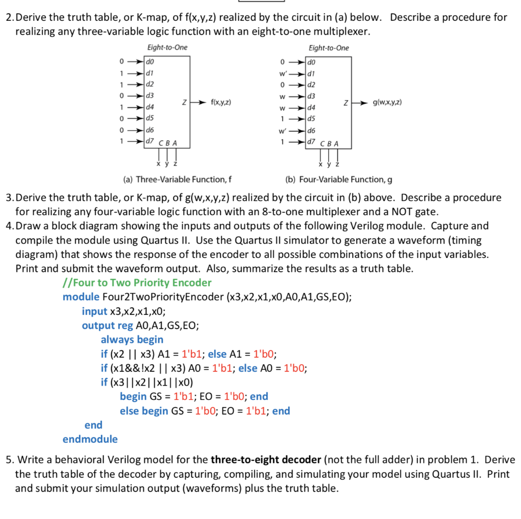
2.Derive the truth table, or K-map, of f(x,y,z) realized by the circuit in (a) below. Describe a procedure for realizing any three-variable logic function with an eight-to-one multiplexer. Eight-to-One Eight-to-One d1 d2 d3 0 d3 d4 f(x,yz) g(wxyz) 0 d6 d7 CBA d7 CBA (a) Three-Variable Function,f (b) Four-Variable Function, g 3.Derive the truth table, or K-map, of g(w,x,y,z) realized by the circuit in (b) above. Describe a procedure for realizing any four-variable logic function with an 8-to-one multiplexer and a NOT gate. 4. Draw a block diagram showing the inputs and outputs of the following Verilog module. Capture and compile the module using Quartus lI. Use the Quartus Il simulator to generate a waveform (timing diagram) that shows the response of the encoder to all possible combinations of the input variables. Print and submit the waveform output. Also, summarize the results as a truth table. //Four to Two Priority Encoder module Four2TwoPriorityEncoder (x3,x2,x1,x0,A0,A1,GS,EO); input x3,x2,x1,x0; output reg A0,A1,GS,EO; always begin if (x2 ||x3) A1 1'b1; else A1 1'b0; if (x1&&lx2 | | x3) AO 1'b1; else AO 1'b0; if (x31|x21 |x1| |x0) begin GS 1'b1; EO 1'b0; end else begin GS 1'b0; EO 1'b1; end end endmodule 5. Write a behavioral Verilog model for the three-to-eight decoder (not the full adder) in problem 1. Derive the truth table of the decoder by capturing, compiling, and simulating your model using Quartus II. Print and submit your simulation output (waveforms) plus the truth table. 2.Derive the truth table, or K-map, of f(x,y,z) realized by the circuit in (a) below. Describe a procedure for realizing any three-variable logic function with an eight-to-one multiplexer. Eight-to-One Eight-to-One d1 d2 d3 0 d3 d4 f(x,yz) g(wxyz) 0 d6 d7 CBA d7 CBA (a) Three-Variable Function,f (b) Four-Variable Function, g 3.Derive the truth table, or K-map, of g(w,x,y,z) realized by the circuit in (b) above. Describe a procedure for realizing any four-variable logic function with an 8-to-one multiplexer and a NOT gate. 4. Draw a block diagram showing the inputs and outputs of the following Verilog module. Capture and compile the module using Quartus lI. Use the Quartus Il simulator to generate a waveform (timing diagram) that shows the response of the encoder to all possible combinations of the input variables. Print and submit the waveform output. Also, summarize the results as a truth table. //Four to Two Priority Encoder module Four2TwoPriorityEncoder (x3,x2,x1,x0,A0,A1,GS,EO); input x3,x2,x1,x0; output reg A0,A1,GS,EO; always begin if (x2 ||x3) A1 1'b1; else A1 1'b0; if (x1&&lx2 | | x3) AO 1'b1; else AO 1'b0; if (x31|x21 |x1| |x0) begin GS 1'b1; EO 1'b0; end else begin GS 1'b0; EO 1'b1; end end endmodule 5. Write a behavioral Verilog model for the three-to-eight decoder (not the full adder) in problem 1. Derive the truth table of the decoder by capturing, compiling, and simulating your model using Quartus II. Print and submit your simulation output (waveforms) plus the truth table