Answered step by step
Verified Expert Solution
Question
1 Approved Answer
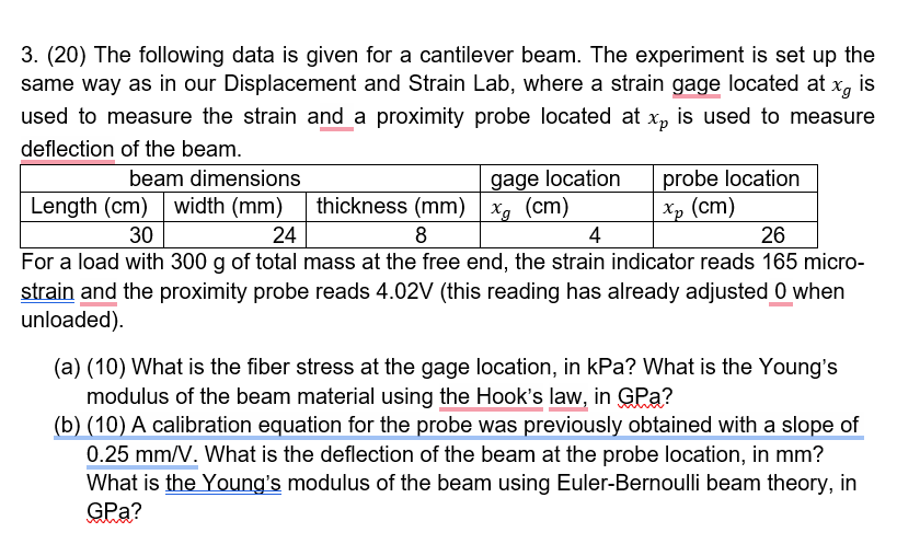
3. (20) The following data is given for a cantilever beam. The experiment is set up the same way as in our Displacement and

3. (20) The following data is given for a cantilever beam. The experiment is set up the same way as in our Displacement and Strain Lab, where a strain gage located at x, is used to measure the strain and a proximity probe located at xp is used to measure deflection of the beam. beam dimensions gage location probe location Length (cm) width (mm) thickness (mm) xg (cm) Xp (cm) 30 8 4 26 24 For a load with 300 g of total mass at the free end, the strain indicator reads 165 micro- strain and the proximity probe reads 4.02V (this reading has already adjusted 0 when unloaded). (a) (10) What is the fiber stress at the gage location, in kPa? What is the Young's modulus of the beam material using the Hook's law, in GPa? (b) (10) A calibration equation for the probe was previously obtained with a slope of 0.25 mm/V. What is the deflection of the beam at the probe location, in mm? What is the Young's modulus of the beam using Euler-Bernoulli beam theory, in GPa?
Step by Step Solution
There are 3 Steps involved in it
Step: 1

Get Instant Access to Expert-Tailored Solutions
See step-by-step solutions with expert insights and AI powered tools for academic success
Step: 2

Step: 3

Ace Your Homework with AI
Get the answers you need in no time with our AI-driven, step-by-step assistance
Get Started


