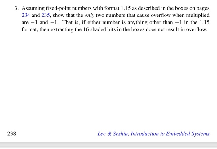
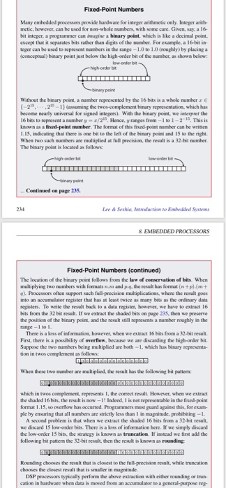
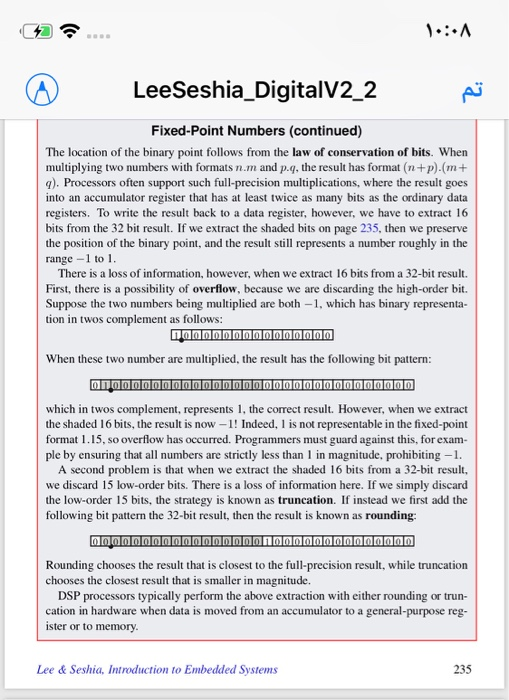
3. Assuming fixed-point numbers with format 1.15 as described in the boxes on pages 234 and 235, show that the only two numbers that cause overflow when multiplied are 1 and -1. That is, if either number is anything other than -1 in the 1.15 format, then extracting the 16 shaded bits in the boxes does not result in overflow. 238 Lee & Seshia, Introduction to Embedded Systems Fixed-Point Numbers Many embedded processors provide hardware for integer arithmetic only. Inteper anith metic, however, can be used for non-whole numbers, with some care. Given, say, a 16- bit integer, a programmer can imagine a binary point, which is like a decimal point. except that it separates bits rather than digits of the nember. For example, a 16-bit in- eger can be used to represcnt numbers in the range - 1.0 to 1.0 (roughly) by placing a (conceptual) binary point just below the high-ceder bit of the sumber, as shown below low-order bit Without the binary point, a number represented by the 16 bits is a whole number r -22-1 (assuming the twos-complement binary representation, which has become nearly universal for signed inlegers), With the binary point, we interpret the 16 bits to represent a number y z/2 Hence, ranges from -1t01-2-15. This is known as a fived-point number. The format of this fixed-point number can be wrimen 1.15, indicating that there is one bit to the left of the binary point and 15 to the right When two such numbers are multiplied at full precision, the result is a 32-bit number The binary point is located as follows: point Centinued on page 235 234 Lee& Seshia Introuction to Embedded Systm The location of the binary point follows from the law of conservation of bits. When multiplying two numbers with formats .m and p.4-the result has format (n + p).(m + g. Processors often suppeet such full-precision multiplications, w here the resalt goes into an accumelator register that has at keast twice as many bits as the ordinary data registers. To write the result back to a dala regislet, however, we have to extract 16 bits from the 32 bit resut. If we extract the shaded bits on page 235S, then we preserve the position of the binary poink, and the result still represents a number oughly in the ranpe -1 to There is a loss of information, however, when we extract 16 bits from a 32-bit result. First, there is a possibility of overflow, because we are discarding the high-onder bit Suppose the two mumbers being multipied are both -1, which has binary rcpeesenta- in twos complement as follows When these two sumber are multiplied, the result has the following bit puttern: which in twos coemplemen, represents I, the correct result. However, when we extract the shaded 16 bits, the result is now-1! Indeed. 1 is not representable in the fixed-point format 1.15, so overfow has occurred. Programmers met guard against this, for exam- ple by ensuring that all numbers are strictly less than 1 in magnitude, probibiting-1 A second problem is that when we extract the shaded 16 bits from a 32-bit result we discard 15 low-order bits. There is a loss of information here. If we simply discard the low-ceder 15 bits, the straegy is known as truncation If isstead we first add the following bit pattern the 32-bit result, then the resul is known as rounding Rounding chooses the result that is closest to the full-precision result, while truncation chooses the closest result that is smaller in magnitude DSP peocessors typically perform the above extraction with either rounding oe trun- cation in hardware when data is moved from an accumulator to a gencral-purpose rep- LeeSeshia_DigitalV2 2 Fixed-Point Numbers (continued) The location of the binary point follows from the law of conservation of bits. When multiplying two numbers with formats n.m and p.q, the result has format (n+p).(m+ q). Processors often support such full-precision multiplications, where the result goes into an accumulator register that has at least twice as many bits as the ordinary data registers. To write the result back to a data register, however, we have to extract 16 bits from the 32 bit result. If we extract the shaded bits on page 235, then we preserve the position of the binary point, and the result still represents a number roughly in the range -1 to 1. There is a loss of information, however, when we extract 16 bits from a 32-bit result. First, there is a possibility of overflow, because we are discarding the high-order bit. Suppose the two numbers being multiplied are both -1, which has binary representa- tion in twos complement as follows: When these two number are multiplied, the result has the following bit pattern: which in twos complement, represents 1, the correct result. However, when we extract the shaded 16 bits, the result is now-1! Indeed, 1 is not representable in the fixed-point format l15, so overflow has occurred. Programmers must guard against this, for exam- ple by ensuring that all numbers are strictly less than 1 in magnitude, prohibiting-1 A second problem is that when we extract the shaded 16 bits from a 32-bit result, we discard 15 low-order bits. There is a loss of information here. If we simply discard the low-order 15 bits, the strategy is known as truncation. If instead we first add the following bit pattern the 32-bit result, then the result is known as rounding: Rounding chooses the result that is closest to the full-precision result, while truncation chooses the closest result that is smaller in magnitude. DSP processors typically perform the above extraction with either rounding or trun- cation in hardware when data is moved from an accumulator to a general-purpose reg- ister or to memory Lee & Seshia, Introduction to Embedded Systems 235 3. Assuming fixed-point numbers with format 1.15 as described in the boxes on pages 234 and 235, show that the only two numbers that cause overflow when multiplied are 1 and -1. That is, if either number is anything other than -1 in the 1.15 format, then extracting the 16 shaded bits in the boxes does not result in overflow. 238 Lee & Seshia, Introduction to Embedded Systems Fixed-Point Numbers Many embedded processors provide hardware for integer arithmetic only. Inteper anith metic, however, can be used for non-whole numbers, with some care. Given, say, a 16- bit integer, a programmer can imagine a binary point, which is like a decimal point. except that it separates bits rather than digits of the nember. For example, a 16-bit in- eger can be used to represcnt numbers in the range - 1.0 to 1.0 (roughly) by placing a (conceptual) binary point just below the high-ceder bit of the sumber, as shown below low-order bit Without the binary point, a number represented by the 16 bits is a whole number r -22-1 (assuming the twos-complement binary representation, which has become nearly universal for signed inlegers), With the binary point, we interpret the 16 bits to represent a number y z/2 Hence, ranges from -1t01-2-15. This is known as a fived-point number. The format of this fixed-point number can be wrimen 1.15, indicating that there is one bit to the left of the binary point and 15 to the right When two such numbers are multiplied at full precision, the result is a 32-bit number The binary point is located as follows: point Centinued on page 235 234 Lee& Seshia Introuction to Embedded Systm The location of the binary point follows from the law of conservation of bits. When multiplying two numbers with formats .m and p.4-the result has format (n + p).(m + g. Processors often suppeet such full-precision multiplications, w here the resalt goes into an accumelator register that has at keast twice as many bits as the ordinary data registers. To write the result back to a dala regislet, however, we have to extract 16 bits from the 32 bit resut. If we extract the shaded bits on page 235S, then we preserve the position of the binary poink, and the result still represents a number oughly in the ranpe -1 to There is a loss of information, however, when we extract 16 bits from a 32-bit result. First, there is a possibility of overflow, because we are discarding the high-onder bit Suppose the two mumbers being multipied are both -1, which has binary rcpeesenta- in twos complement as follows When these two sumber are multiplied, the result has the following bit puttern: which in twos coemplemen, represents I, the correct result. However, when we extract the shaded 16 bits, the result is now-1! Indeed. 1 is not representable in the fixed-point format 1.15, so overfow has occurred. Programmers met guard against this, for exam- ple by ensuring that all numbers are strictly less than 1 in magnitude, probibiting-1 A second problem is that when we extract the shaded 16 bits from a 32-bit result we discard 15 low-order bits. There is a loss of information here. If we simply discard the low-ceder 15 bits, the straegy is known as truncation If isstead we first add the following bit pattern the 32-bit result, then the resul is known as rounding Rounding chooses the result that is closest to the full-precision result, while truncation chooses the closest result that is smaller in magnitude DSP peocessors typically perform the above extraction with either rounding oe trun- cation in hardware when data is moved from an accumulator to a gencral-purpose rep- LeeSeshia_DigitalV2 2 Fixed-Point Numbers (continued) The location of the binary point follows from the law of conservation of bits. When multiplying two numbers with formats n.m and p.q, the result has format (n+p).(m+ q). Processors often support such full-precision multiplications, where the result goes into an accumulator register that has at least twice as many bits as the ordinary data registers. To write the result back to a data register, however, we have to extract 16 bits from the 32 bit result. If we extract the shaded bits on page 235, then we preserve the position of the binary point, and the result still represents a number roughly in the range -1 to 1. There is a loss of information, however, when we extract 16 bits from a 32-bit result. First, there is a possibility of overflow, because we are discarding the high-order bit. Suppose the two numbers being multiplied are both -1, which has binary representa- tion in twos complement as follows: When these two number are multiplied, the result has the following bit pattern: which in twos complement, represents 1, the correct result. However, when we extract the shaded 16 bits, the result is now-1! Indeed, 1 is not representable in the fixed-point format l15, so overflow has occurred. Programmers must guard against this, for exam- ple by ensuring that all numbers are strictly less than 1 in magnitude, prohibiting-1 A second problem is that when we extract the shaded 16 bits from a 32-bit result, we discard 15 low-order bits. There is a loss of information here. If we simply discard the low-order 15 bits, the strategy is known as truncation. If instead we first add the following bit pattern the 32-bit result, then the result is known as rounding: Rounding chooses the result that is closest to the full-precision result, while truncation chooses the closest result that is smaller in magnitude. DSP processors typically perform the above extraction with either rounding or trun- cation in hardware when data is moved from an accumulator to a general-purpose reg- ister or to memory Lee & Seshia, Introduction to Embedded Systems 235


