

Answered step by step
Verified Expert Solution
Question
1 Approved Answer
3. Consider the following circuit with the voltage vs as the control input and i as the disturbance input m L C R a)
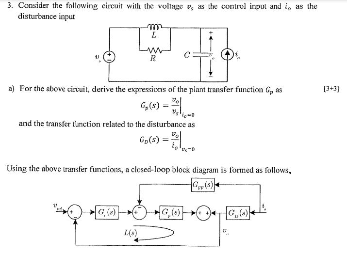
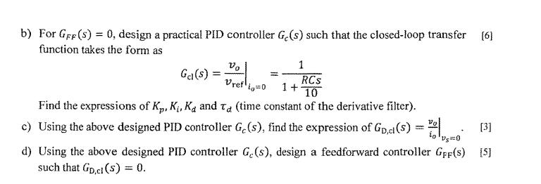
3. Consider the following circuit with the voltage vs as the control input and i as the disturbance input m L C R a) For the above circuit, derive the expressions of the plant transfer function G, as Vo Gp(s): == and the transfer function related to the disturbance as Vo GD(S) = Using the above transfer functions, a closed-loop block diagram is formed as follows. GF (S) FF rd + G(s) + G (8) ++) G(s) L(s) " [3+3] b) For GFF (S) = 0, design a practical PID controller Ge(s) such that the closed-loop transfer [6] function takes the form as Ga(s) = ==== Vo Vref 1 == RCS 1+ 10 Find the expressions of K, K, Ka and Ta (time constant of the derivative filter). c) Using the above designed PID controller G,(s), find the expression of GD,cl(s) = 100 | [3] d) Using the above designed PID controller G,(s), design a feedforward controller GFF(s) [5] such that Gp,cl(s) = 0.
Step by Step Solution
There are 3 Steps involved in it
Step: 1

Get Instant Access to Expert-Tailored Solutions
See step-by-step solutions with expert insights and AI powered tools for academic success
Step: 2

Step: 3
Ace Your Homework with AI
Get the answers you need in no time with our AI-driven, step-by-step assistance
Get Started
Elements Of Chemical Reaction Engineering
Authors: H. Fogler
6th Edition
013548622X, 978-0135486221