

Answered step by step
Verified Expert Solution
Question
1 Approved Answer
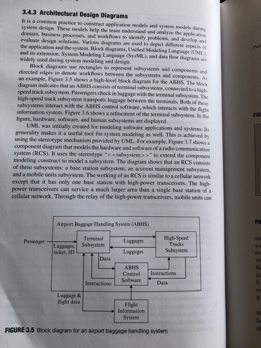
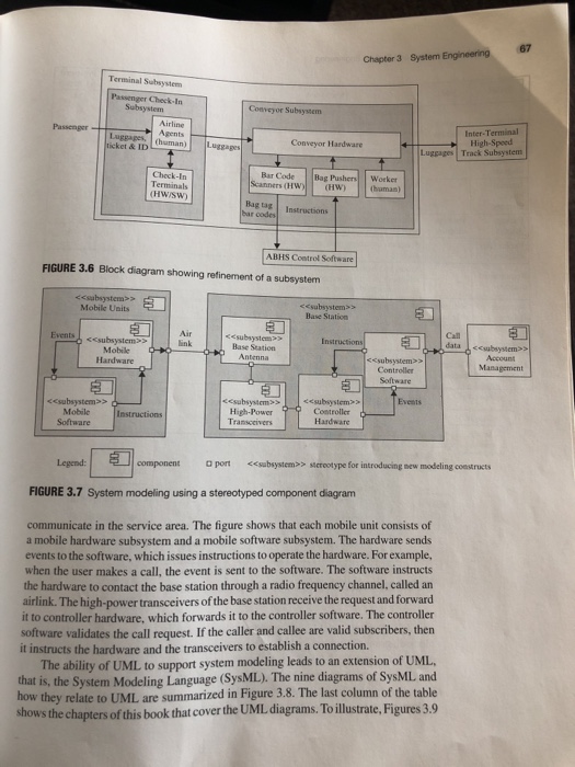
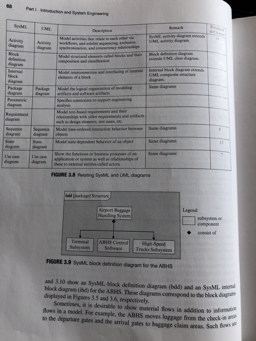
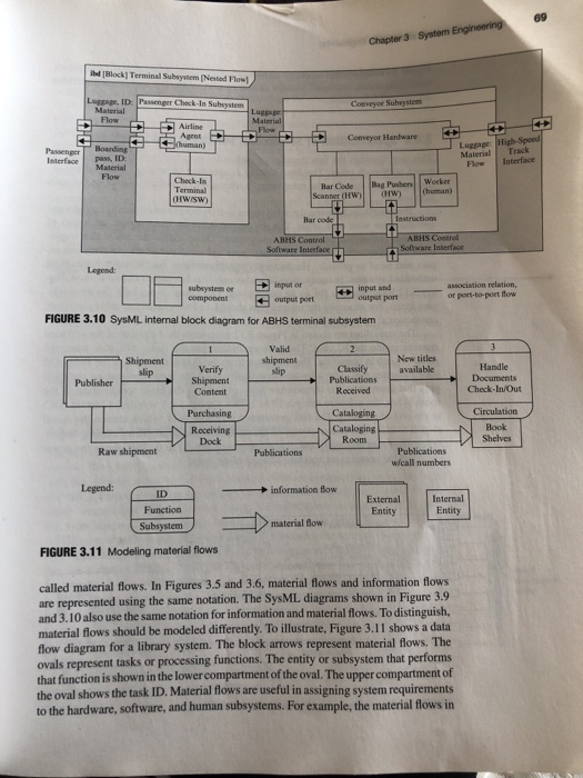
3.4.3 Architectural Design Diagrams It is a common practice to construct application models and system models during system design. These models help the team understand
Step by Step Solution
There are 3 Steps involved in it
Step: 1

Get Instant Access to Expert-Tailored Solutions
See step-by-step solutions with expert insights and AI powered tools for academic success
Step: 2

Step: 3
Ace Your Homework with AI
Get the answers you need in no time with our AI-driven, step-by-step assistance
Get Started
Database Concepts
Authors: David M. Kroenke, David J. Auer
7th edition
133544621, 133544626, 0-13-354462-1, 978-0133544626