

Answered step by step
Verified Expert Solution
Question
1 Approved Answer
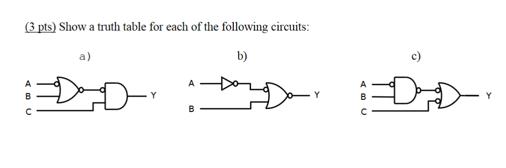
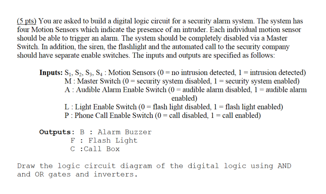
(3pts) Show a truth table for each of the following circuits: a) b) (5 pts) You are asked to build a digital logic circuit for
Step by Step Solution
There are 3 Steps involved in it
Step: 1

Get Instant Access to Expert-Tailored Solutions
See step-by-step solutions with expert insights and AI powered tools for academic success
Step: 2

Step: 3
Ace Your Homework with AI
Get the answers you need in no time with our AI-driven, step-by-step assistance
Get Started
Big Data And Hadoop Fundamentals Tools And Techniques For Data Driven Success
Authors: Mayank Bhushan
2nd Edition
9355516665, 978-9355516664