Answered step by step
Verified Expert Solution
Link Copied!

Question

1 Approved Answer

4. (a) Use the three-step approach to analyze the circuit in Figure 4 (excitation/output equations, state/output table, and state diagram). Keep the state in numeric
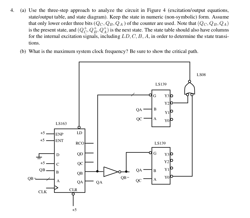
image text in transcribed

4. (a) Use the three-step approach to analyze the circuit in Figure 4 (excitation/output equations, state/output table, and state diagram). Keep the state in numeric (non-symbolic) form. Assume that only lower order three bits (Qc, QB, QA) of the counter are used. Note that (Qc, QB, QA) is the present state, and (Q s the next state. The state table should also have columns for the internal excitation signals, including LD, C, B, A, in order to determine the state transi tions (b) What is the maximum system clock frequency? Be sure to show the critical path LSO8 LS139 G Y3 Y2 QAB QCA LS163 LD ENP ENT RCO LS139 QD G Y Y2 B YI QCA YO QA QB QB QB- QA QA CLR CLK

Step by Step Solution

There are 3 Steps involved in it

Step: 1

blur-text-image

Get Instant Access to Expert-Tailored Solutions

See step-by-step solutions with expert insights and AI powered tools for academic success

Step: 2

blur-text-image_step_2

Step: 3

blur-text-image_step3

Ace Your Homework with AI

Get the answers you need in no time with our AI-driven, step-by-step assistance

Get Started

Recommended Textbook for

More Books

Students also viewed these Databases questions