Answered step by step
Verified Expert Solution
Question
1 Approved Answer
4. Absorber column design for solvent CO2 capture (25 points) A solvent absorption column is to be used to remove carbon dioxide from the


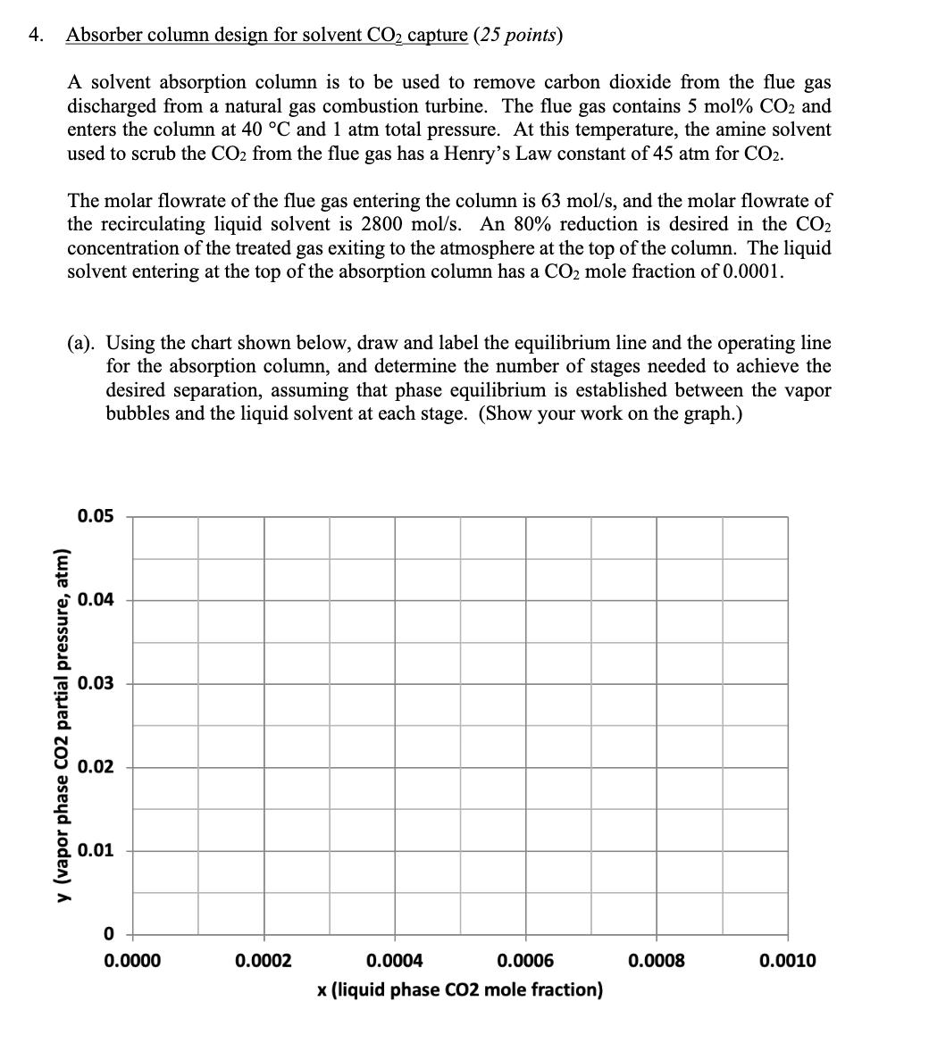
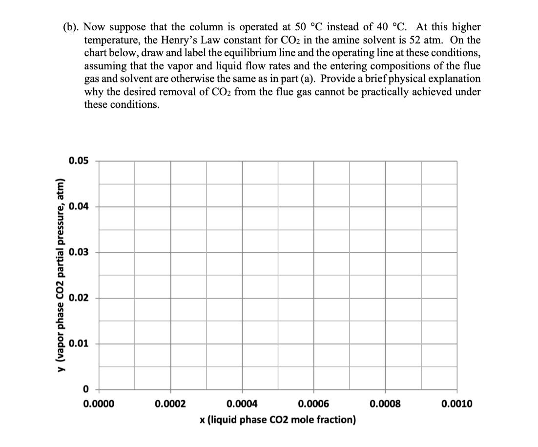
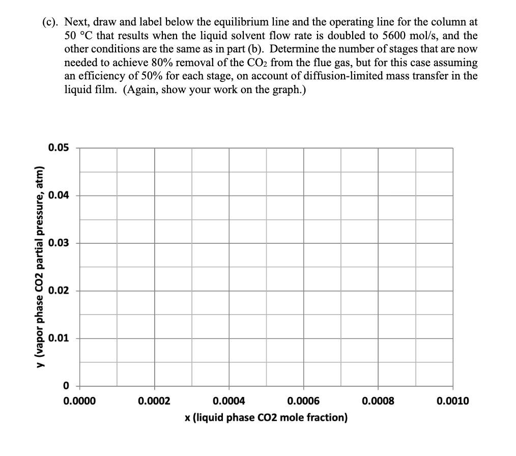
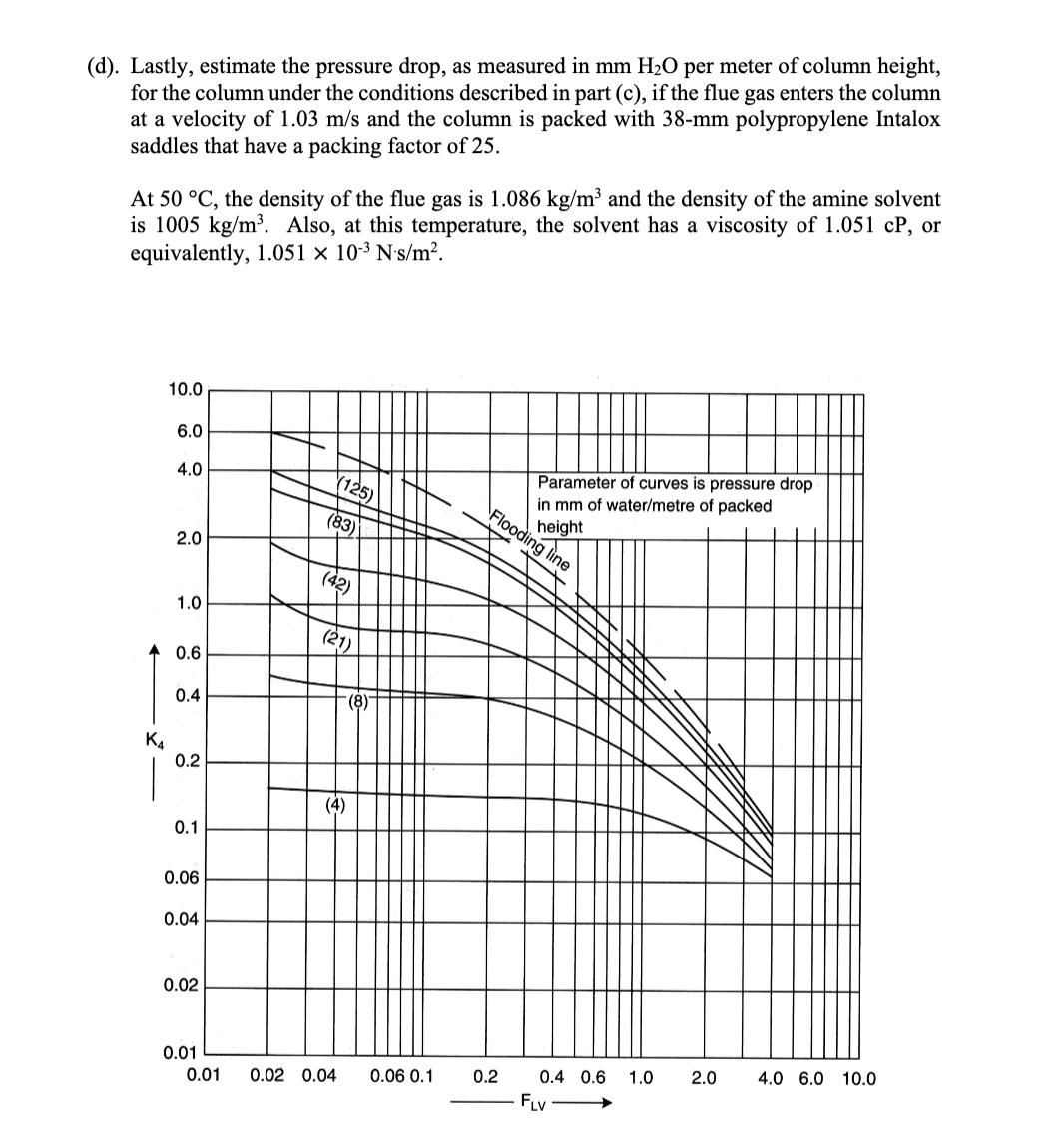
4. Absorber column design for solvent CO2 capture (25 points) A solvent absorption column is to be used to remove carbon dioxide from the flue gas discharged from a natural gas combustion turbine. The flue gas contains 5 mol% CO2 and enters the column at 40 C and 1 atm total pressure. At this temperature, the amine solvent used to scrub the CO2 from the flue gas has a Henry's Law constant of 45 atm for CO2. The molar flowrate of the flue gas entering the column is 63 mol/s, and the molar flowrate of the recirculating liquid solvent is 2800 mol/s. An 80% reduction is desired in the CO2 concentration of the treated gas exiting to the atmosphere at the top of the column. The liquid solvent entering at the top of the absorption column has a CO2 mole fraction of 0.0001. (a). Using the chart shown below, draw and label the equilibrium line and the operating line for the absorption column, and determine the number of stages needed to achieve the desired separation, assuming that phase equilibrium is established between the vapor bubbles and the liquid solvent at each stage. (Show your work on the graph.) 0.05 0.04 0.03 y (vapor phase CO2 partial pressure, atm) 0.02 0.01 0 0.0000 0.0002 0.0004 0.0006 0.0008 0.0010 x (liquid phase CO2 mole fraction) (b). Now suppose that the column is operated at 50 C instead of 40 C. At this higher temperature, the Henry's Law constant for CO2 in the amine solvent is 52 atm. On the chart below, draw and label the equilibrium line and the operating line at these conditions, assuming that the vapor and liquid flow rates and the entering compositions of the flue gas and solvent are otherwise the same as in part (a). Provide a brief physical explanation why the desired removal of CO2 from the flue gas cannot be practically achieved under these conditions. 0.05 0.04 0.03 y (vapor phase CO2 partial pressure, atm) 0.02 0.01 0 od 0.0000 0.0002 0.0004 0.0006 0.0008 0.0010 x (liquid phase CO2 mole fraction) (c). Next, draw and label below the equilibrium line and the operating line for the column at 50 C that results when the liquid solvent flow rate is doubled to 5600 mol/s, and the other conditions are the same as in part (b). Determine the number of stages that are now needed to achieve 80% removal of the CO2 from the flue gas, but for this case assuming an efficiency of 50% for each stage, on account of diffusion-limited mass transfer in the liquid film. (Again, show your work on the graph.) 0.05 0.04 0.03 y (vapor phase CO2 partial pressure, atm) 0.02 0.01 0 0.0000 0.0002 0.0004 0.0006 x (liquid phase CO2 mole fraction) 0.0008 0.0010 (d). Lastly, estimate the pressure drop, as measured in mm H2O per meter of column height, for the column under the conditions described in part (c), if the flue gas enters the column at a velocity of 1.03 m/s and the column is packed with 38-mm polypropylene Intalox saddles that have a packing factor of 25. At 50 C, the density of the flue gas is 1.086 kg/m and the density of the amine solvent is 1005 kg/m. Also, at this temperature, the solvent has a viscosity of 1.051 CP, or equivalently, 1.051 10-3 N's/m. 10.0 6.0 4.0 (125) (83) Flooding line 2.0 (42) 1.0 (21) 0.6 (8)- 0.4 K4 0.2 (4) 0.1 0.06 0.04 0.02 Parameter of curves is pressure drop in mm of water/metre of packed height 0.01 0.01 0.02 0.04 0.06 0.1 0.2 0.4 0.6 1.0 2.0 4.0 6.0 10.0 FLV
Step by Step Solution
There are 3 Steps involved in it
Step: 1

Get Instant Access to Expert-Tailored Solutions
See step-by-step solutions with expert insights and AI powered tools for academic success
Step: 2

Step: 3

Ace Your Homework with AI
Get the answers you need in no time with our AI-driven, step-by-step assistance
Get Started


