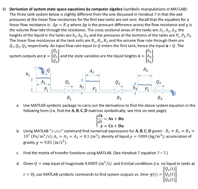
4) Derivation of system state space equations by computer algebra (symbolic manipulations in MATLAB) The three tank system below is slightly different from the one discussed in Handout 7 in that the exit pressures at the linear flow resistances for the first two tanks are not zero. Recall that the equation for a linear flow resistance is: ?p R q where ?p is the pressure difference across the flow resistance and q is the volume flow rate through the resistance. The cross sectional areas of the tanks are A,Az A3; the heights of the liquid in the tanks are h1,h2, h3 and the pressures at the bottoms of the tanks are P, P2, P3 The linear flow resistances at the tank exits are R1, R2, R3 and the volume flow rate through them are 01,Q2,03 respectively. An input flow rate equal to Q enters the first tank, hence the input u-Q. The system outputs are y 02 and the state variables are the liquid heights x -h2 Q1 02 Q3 Use MATLAB symbolic package to carry out the derivations to find the above system equation in the following form (i.e. find the A, B, C, D matrices symbolically; see Hint on next page) a. Ax Bu dt y = Cx + Du R1R2-R3 - Using MATLAB "subs" command find numerical expressions for A, B, C, D given: 107 (Pa/ m3/s); Al-A2-A3-0.1 (m?); density of liquid gravity g 9.81 (m/s2) b. 1000 (kg/m"); acceleration of Find the matrix of transfer functions using MATLAB. See Handout 7 equation 7- 7.) Given Q t0), use MATLAB symbolic commands to find system outputs vs. time: y(t) -Q2(t) c. d. step input of magnitude 0.0005 (m3/s) and 0 initial conditions (i.e. no liquid in tanks at 01(t) Qs(t) 4) Derivation of system state space equations by computer algebra (symbolic manipulations in MATLAB) The three tank system below is slightly different from the one discussed in Handout 7 in that the exit pressures at the linear flow resistances for the first two tanks are not zero. Recall that the equation for a linear flow resistance is: ?p R q where ?p is the pressure difference across the flow resistance and q is the volume flow rate through the resistance. The cross sectional areas of the tanks are A,Az A3; the heights of the liquid in the tanks are h1,h2, h3 and the pressures at the bottoms of the tanks are P, P2, P3 The linear flow resistances at the tank exits are R1, R2, R3 and the volume flow rate through them are 01,Q2,03 respectively. An input flow rate equal to Q enters the first tank, hence the input u-Q. The system outputs are y 02 and the state variables are the liquid heights x -h2 Q1 02 Q3 Use MATLAB symbolic package to carry out the derivations to find the above system equation in the following form (i.e. find the A, B, C, D matrices symbolically; see Hint on next page) a. Ax Bu dt y = Cx + Du R1R2-R3 - Using MATLAB "subs" command find numerical expressions for A, B, C, D given: 107 (Pa/ m3/s); Al-A2-A3-0.1 (m?); density of liquid gravity g 9.81 (m/s2) b. 1000 (kg/m"); acceleration of Find the matrix of transfer functions using MATLAB. See Handout 7 equation 7- 7.) Given Q t0), use MATLAB symbolic commands to find system outputs vs. time: y(t) -Q2(t) c. d. step input of magnitude 0.0005 (m3/s) and 0 initial conditions (i.e. no liquid in tanks at 01(t) Qs(t)


