Question
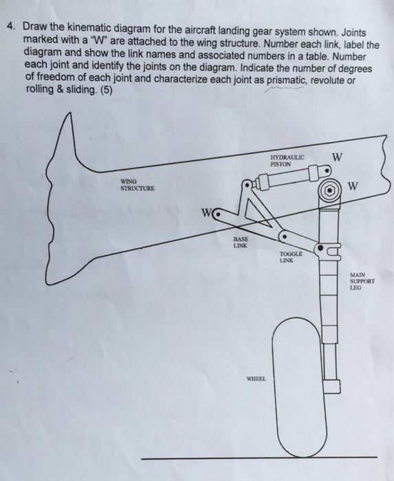
4. Draw the kinematic diagram for the aircraft landing gear system shown. Joints marked with a W are attached to the wing structure. Number

4. Draw the kinematic diagram for the aircraft landing gear system shown. Joints marked with a "W" are attached to the wing structure. Number each link, label the diagram and show the link names and associated numbers in a table. Number each joint and identify the joints on the diagram. Indicate the number of degrees of freedom of each joint and characterize each joint as prismatic, revolute or rolling & sliding. (5) WING STRUCTURE W BASE LINK WHEEL HYDRAULIC PISTON TOGGLE LINK W W MAIN SUPPORT LEG
Step by Step Solution
3.34 Rating (154 Votes )
There are 3 Steps involved in it
Step: 1
Joints J 2 0013 J3 Ju Ju 1 Links 4...
Get Instant Access to Expert-Tailored Solutions
See step-by-step solutions with expert insights and AI powered tools for academic success
Step: 2

Step: 3

Ace Your Homework with AI
Get the answers you need in no time with our AI-driven, step-by-step assistance
Get StartedRecommended Textbook for
Discrete and Combinatorial Mathematics An Applied Introduction
Authors: Ralph P. Grimaldi
5th edition
201726343, 978-0201726343
Students also viewed these Mechanical Engineering questions
Question
Answered: 1 week ago
Question
Answered: 1 week ago
Question
Answered: 1 week ago
Question
Answered: 1 week ago
Question
Answered: 1 week ago
Question
Answered: 1 week ago
Question
Answered: 1 week ago
Question
Answered: 1 week ago
Question
Answered: 1 week ago
Question
Answered: 1 week ago
Question
Answered: 1 week ago
Question
Answered: 1 week ago
Question
Answered: 1 week ago
Question
Answered: 1 week ago
Question
Answered: 1 week ago
Question
Answered: 1 week ago
Question
Answered: 1 week ago
Question
Answered: 1 week ago
Question
Answered: 1 week ago
Question
Answered: 1 week ago
Question
Answered: 1 week ago
View Answer in SolutionInn App


