Answered step by step
Verified Expert Solution
Question
1 Approved Answer
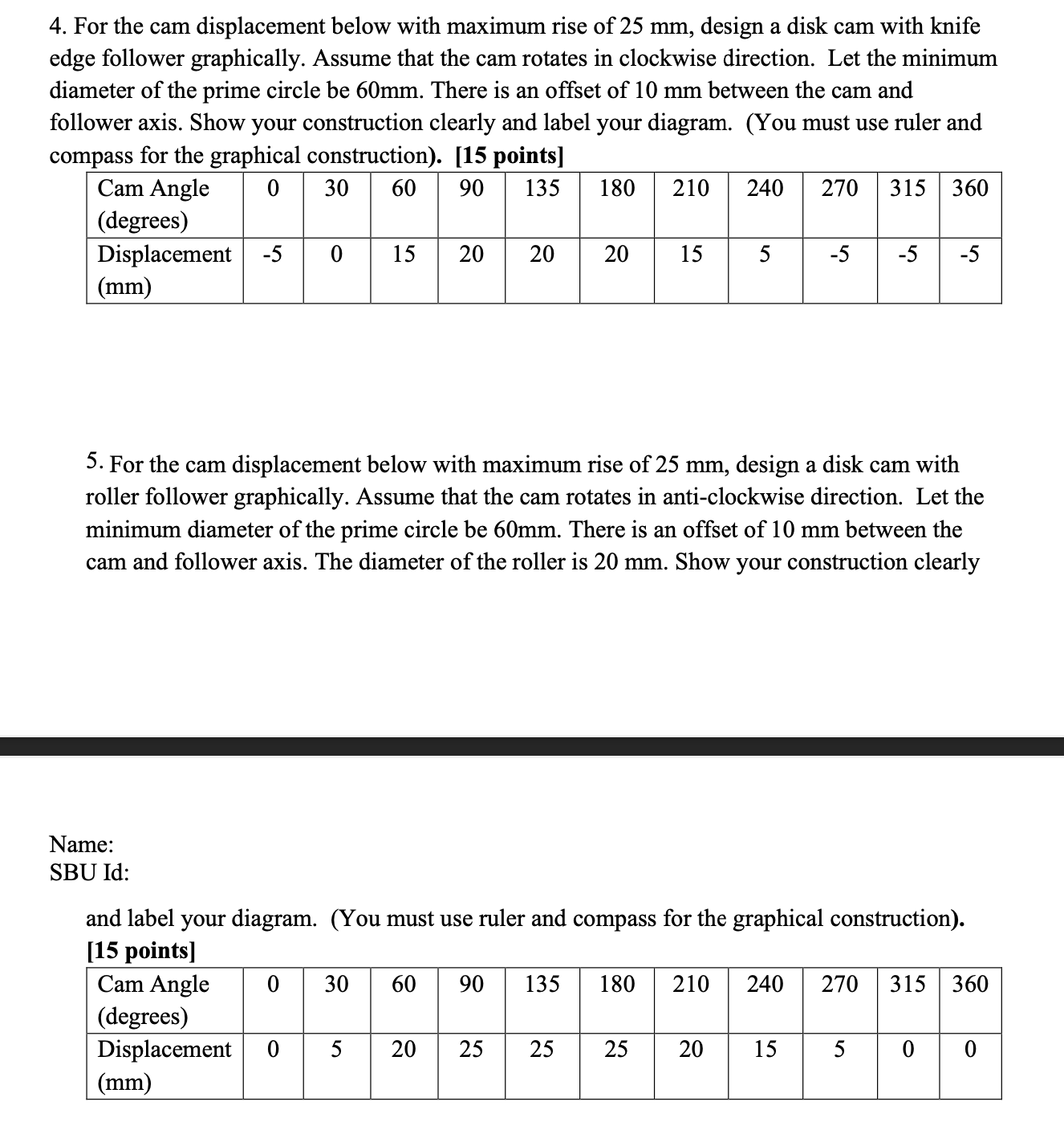
4. For the cam displacement below with maximum rise of 25 mm, design a disk cam with knife edge follower graphically. Assume that the

4. For the cam displacement below with maximum rise of 25 mm, design a disk cam with knife edge follower graphically. Assume that the cam rotates in clockwise direction. Let the minimum diameter of the prime circle be 60mm. There is an offset of 10 mm between the cam and follower axis. Show your construction clearly and label your diagram. (You must use ruler and compass for the graphical construction). [15 points] Cam Angle (degrees) 030 60 90 135 180 210 240 270 315 360 Displacement -5 0 15 20 20 20 20 15 5 -5 -5 -5 (mm) 5. For the cam displacement below with maximum rise of 25 mm, design a disk cam with roller follower graphically. Assume that the cam rotates in anti-clockwise direction. Let the minimum diameter of the prime circle be 60mm. There is an offset of 10 mm between the cam and follower axis. The diameter of the roller is 20 mm. Show your construction clearly Name: SBU Id: and label your diagram. (You must use ruler and compass for the graphical construction). [15 points] Cam Angle 0 30 60 90 1 135 180 210 240 270 315 360 (degrees) Displacement 0 5 20 20 25 25 25 20 15 5 0 0 (mm)
Step by Step Solution
There are 3 Steps involved in it
Step: 1

Get Instant Access to Expert-Tailored Solutions
See step-by-step solutions with expert insights and AI powered tools for academic success
Step: 2

Step: 3

Ace Your Homework with AI
Get the answers you need in no time with our AI-driven, step-by-step assistance
Get Started


