Answered step by step
Verified Expert Solution
Question
1 Approved Answer
4. Geometry, mesh, boundary conditions and Numerical method. You should show the established geometry of your model, the mesh with the number of nodes


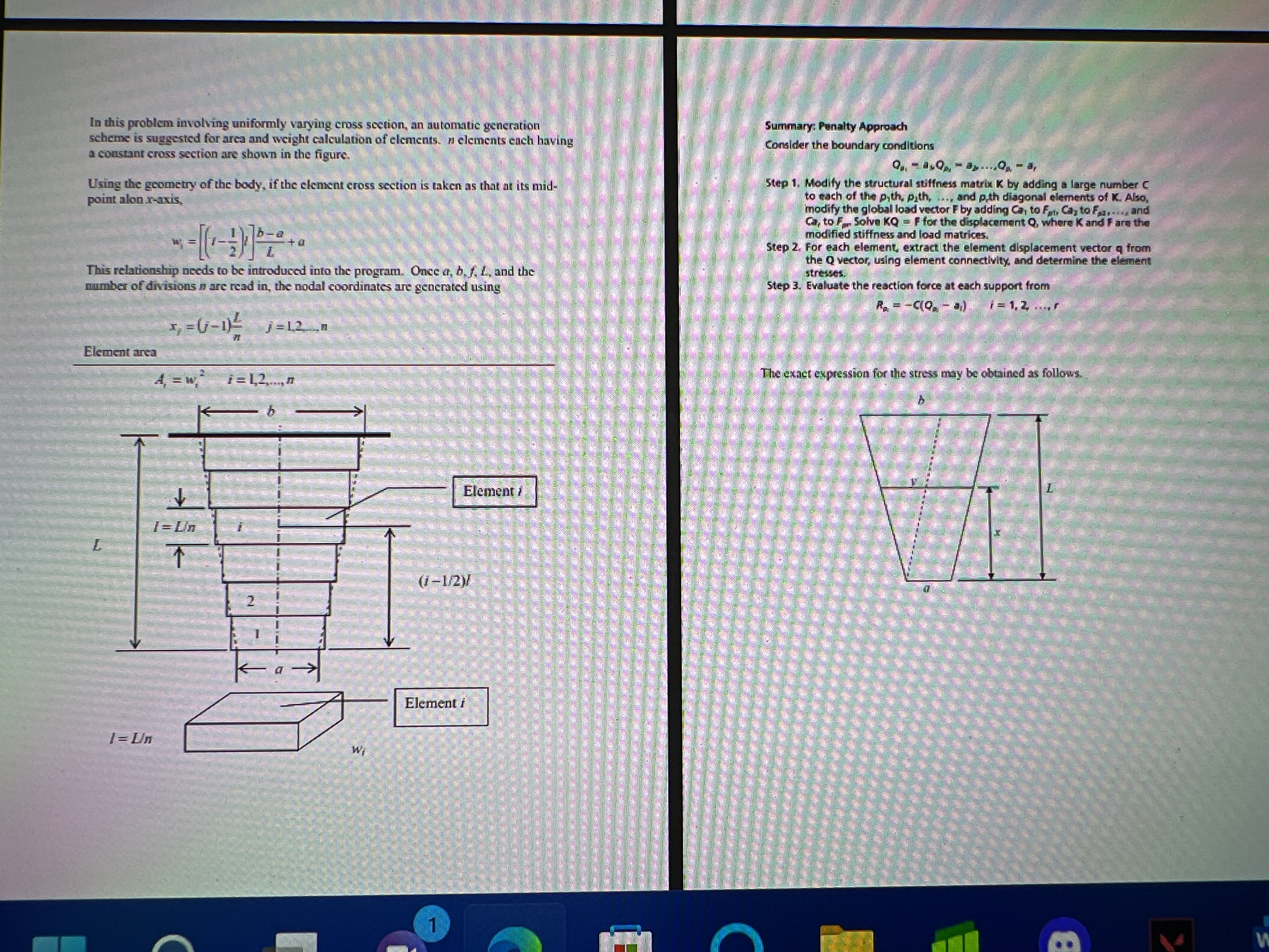
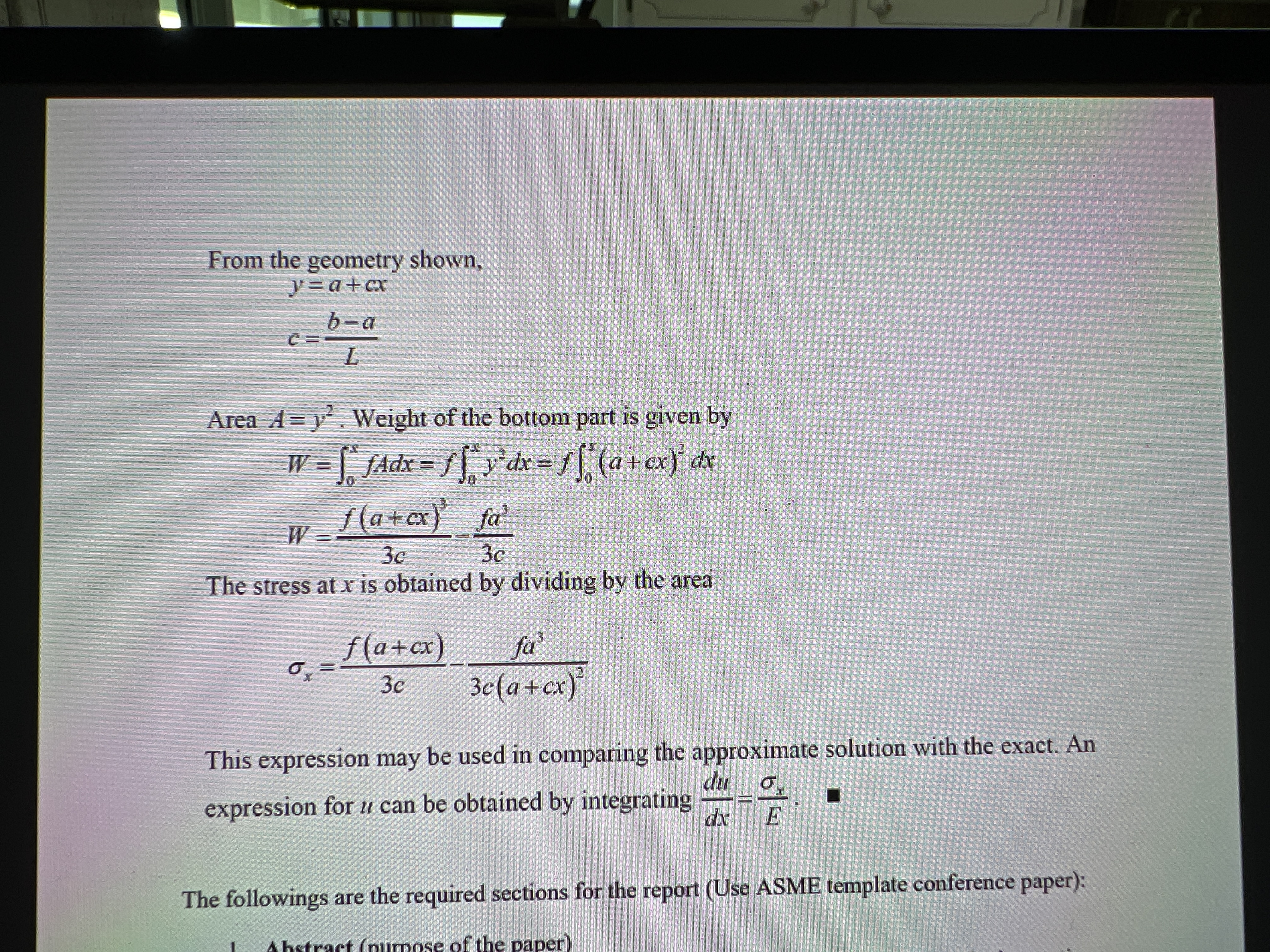
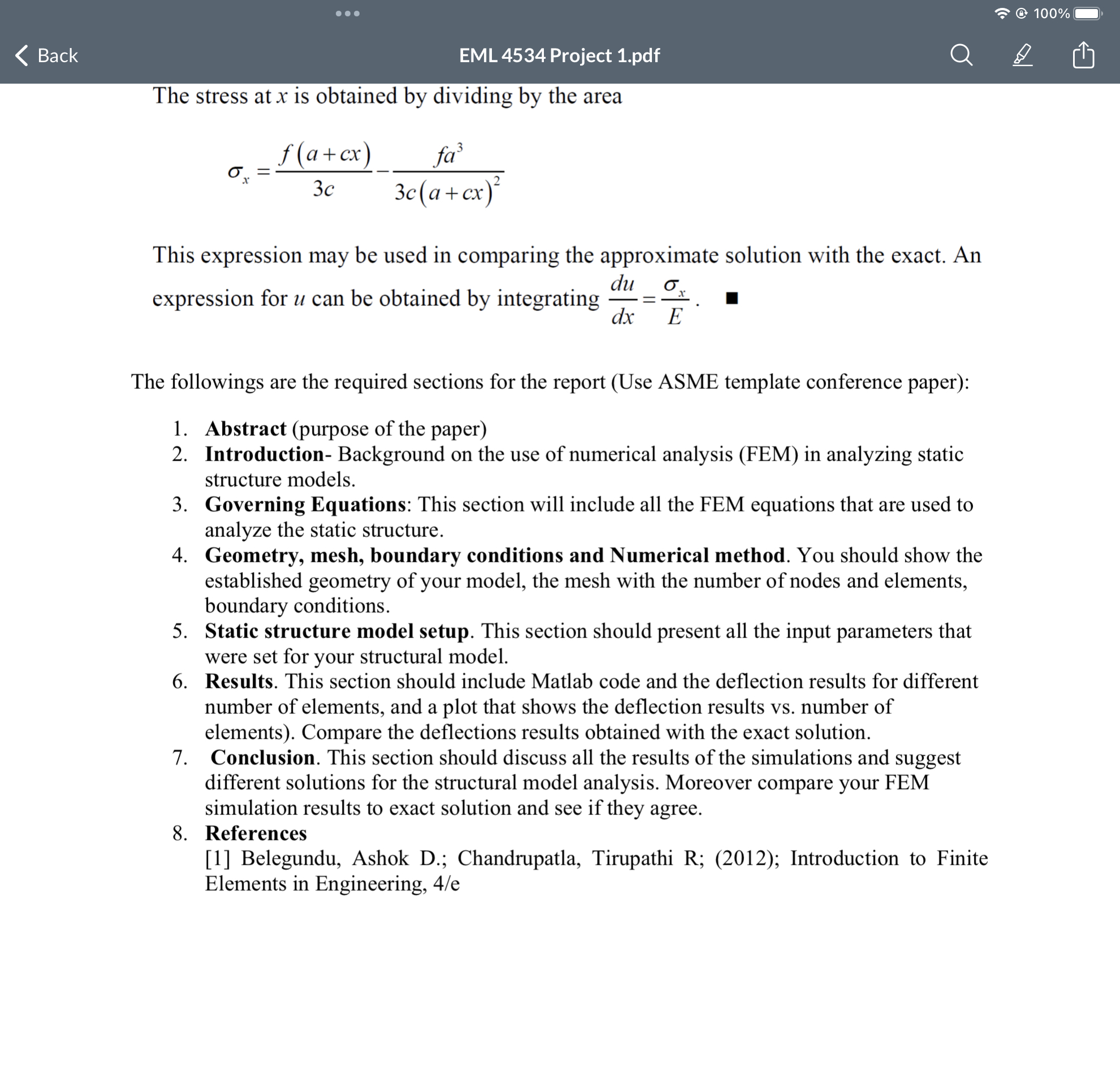
4. Geometry, mesh, boundary conditions and Numerical method. You should show the established geometry of your model, the mesh with the number of nodes and elements, boundary conditions. 5. Static structure model setup. This section should present all the input parameters that were set for your structural model. 6. Results. This section should include Matlab code and the deflection results for different number of aments and lot that shows the deflection resulta. number of In this problem involving uniformly varying cross section, an automatic generation scheme is suggested for area and weight calculation of elements. n elements each having a constant cross section are shown in the figure. Using the geometry of the body, if the element cross section is taken as that at its mid- point alon x-axis This relationship needs to be introduced into the program. Once a, b. f. L, and the number of divisions n are read in, the nodal coordinates are generated using x = (-1) = 12n Summary: Penalty Approach Consider the boundary conditions QQ-ay... Qp-a, Step 1. Modify the structural stiffness matrix K by adding a large number C to each of the pith, pith,..., and p,th diagonal elements of K. Also, modify the global load vector F by adding Ca, to Fm Ca, to F. and Ca, to F Solve KQ = F for the displacement Q, where K and Fare the modified stiffness and load matrices. Step 2. For each element, extract the element displacement vector q from the Q vector, using element connectivity, and determine the element stresses Step 3. Evaluate the reaction force at each support from R = -C(Q-) = 1,2....! Element area A = w 1= Un 1=Un i=42,0 b a Wi Element (1-1/2) Element i 1 The exact expression for the stress may be obtained as follows. B From the geometry shown, y=a+cx b-a c = L Area Ay. Weight of the bottom part is given by W = Adx = y dx = f* (a + ex)* dx f(a+cx) fa W = 3c 3c The stress at x is obtained by dividing by the area f(a+cx) fa 3c 3c (a+cx) This expression may be used in comparing the approximate solution with the exact. An expression for u can be obtained by integrating du dx E The followings are the required sections for the report (Use ASME template conference paper): Abstract (purpose of the paper) @ 100% EML 4534 Project 1.pdf Back The stress at x is obtained by dividing by the area f(a+cx) x 3c fa 3c (a+cx) This expression may be used in comparing the approximate solution with the exact. An expression for u can be obtained by integrating du = dx E The followings are the required sections for the report (Use ASME template conference paper): 1. Abstract (purpose of the paper) 2. Introduction- Background on the use of numerical analysis (FEM) in analyzing static structure models. 3. Governing Equations: This section will include all the FEM equations that are used to analyze the static structure. 4. Geometry, mesh, boundary conditions and Numerical method. You should show the established geometry of your model, the mesh with the number of nodes and elements, boundary conditions. 5. Static structure model setup. This section should present all the input parameters that were set for your structural model. 6. Results. This section should include Matlab code and the deflection results for different number of elements, and a plot that shows the deflection results vs. number of elements). Compare the deflections results obtained with the exact solution. 7. Conclusion. This section should discuss all the results of the simulations and suggest different solutions for the structural model analysis. Moreover compare your FEM simulation results to exact solution and see if they agree. 8. References [1] Belegundu, Ashok D.; Chandrupatla, Tirupathi R; (2012); Introduction to Finite Elements in Engineering, 4/e
Step by Step Solution
There are 3 Steps involved in it
Step: 1

Get Instant Access to Expert-Tailored Solutions
See step-by-step solutions with expert insights and AI powered tools for academic success
Step: 2

Step: 3

Ace Your Homework with AI
Get the answers you need in no time with our AI-driven, step-by-step assistance
Get Started


