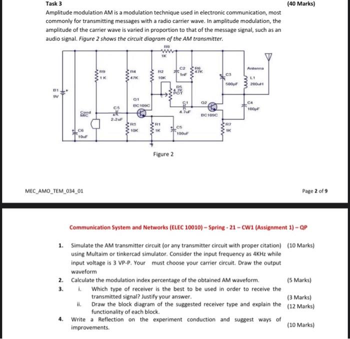
(40 Marks) Task 3 Amplitude modulation AM is a modulation technique used in electronic communication, most commonly for transmitting messages with a radio carrier wave. In amplitude modulation, the amplitude of the carrier wave is varied in proportion to that of the message signal, such as an audio signal. Figure 2 shows the circuit diagram of the AM transmitter. RO ww R4 RE 47K R2 TOK ww IK ca Antenna LI 2001 500 31 V 01 UC1000 02 cs CA 100pF 47 Cond MC C100C 2.2 ur R1 IK R7 IK 10K CS 100F CG Tour Figure 2 MEC_AMO_TEM_034_01 Page 2 of 9 Communication System and Networks (ELEC 10010) - Spring -21-CW1 (Assignment 1) - QP 1. Simulate the AM transmitter circuit (or any transmitter circuit with proper citation) (10 Marks) using Multaim or tinkercad simulator. Consider the input frequency as 4KHz while input voltage is 3 VP-P. Your must choose your carrier circuit. Draw the output waveform 2. Calculate the modulation index percentage of the obtained AM waveform (5 Marks) 3. Which type of receiver is the best to be used in order to receive the transmitted signal? Justify your answer. (3 Marks) ii. Draw the block diagram of the suggested receiver type and explain the (12 Marks) functionality of each block. 4. Write a Reflection on the experiment conduction and suggest ways of improvements. (10 Marks) (40 Marks) Task 3 Amplitude modulation AM is a modulation technique used in electronic communication, most commonly for transmitting messages with a radio carrier wave. In amplitude modulation, the amplitude of the carrier wave is varied in proportion to that of the message signal, such as an audio signal. Figure 2 shows the circuit diagram of the AM transmitter. RO ww R4 RE 47K R2 TOK ww IK ca Antenna LI 2001 500 31 V 01 UC1000 02 cs CA 100pF 47 Cond MC C100C 2.2 ur R1 IK R7 IK 10K CS 100F CG Tour Figure 2 MEC_AMO_TEM_034_01 Page 2 of 9 Communication System and Networks (ELEC 10010) - Spring -21-CW1 (Assignment 1) - QP 1. Simulate the AM transmitter circuit (or any transmitter circuit with proper citation) (10 Marks) using Multaim or tinkercad simulator. Consider the input frequency as 4KHz while input voltage is 3 VP-P. Your must choose your carrier circuit. Draw the output waveform 2. Calculate the modulation index percentage of the obtained AM waveform (5 Marks) 3. Which type of receiver is the best to be used in order to receive the transmitted signal? Justify your answer. (3 Marks) ii. Draw the block diagram of the suggested receiver type and explain the (12 Marks) functionality of each block. 4. Write a Reflection on the experiment conduction and suggest ways of improvements. (10 Marks)