Answered step by step
Verified Expert Solution
Question
1 Approved Answer
A 1-story, 1-span structure shown in the figure below (Isometric view and Fig. 3) is proposed to be constructed. Structure consists of the following


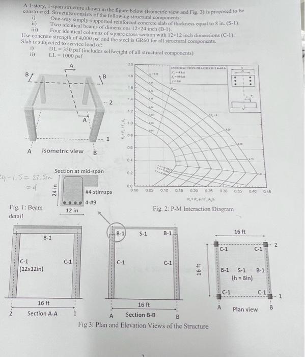
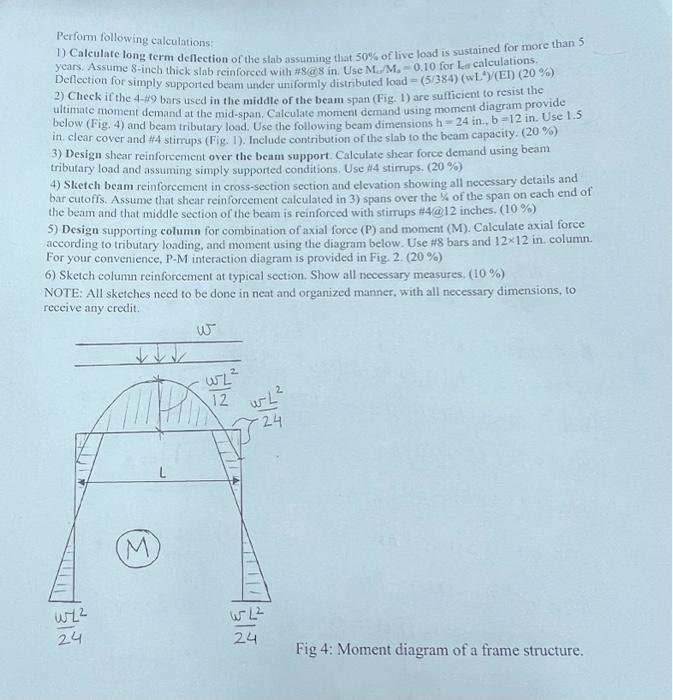
A 1-story, 1-span structure shown in the figure below (Isometric view and Fig. 3) is proposed to be constructed. Structure consists of the following structural components: i) One-way simply-supported reinforced concrete slab of thickness equal to 8 in. (S-1) ii) Two identical beams of dimensions 12-24 inch (B-1). iii) Four identical columns of square cross-section with 12-12 inch dimensions (C-1). Use concrete strength of 4,000 psi and the steel is GR60 for all structural components. Slab is subjected to service load of: i) ii) DL 350 psf (includes selfweight of all structural components) LL-1000 psf B KAINA 20 15 16 14 12 1.0 0.8 1 0.5 A Isometric view B 0.4 Section at mid-span 0.2 4-1.5 = 27. Sin =d 24 in Fig. 1: Beam detail C-1 (12x12in) B-1 12 in INTERACTION DIAGRAM L4sts 00 #4 stirrups 0.00 0.05 0.10 0.15 0:20 0.25 0.30 0.35 0.40 045 R+P+/AM 4-#9 Fig. 2: P-M Interaction Diagram B-1 5-1 B-1 C-1 C-1 C-1 16 ft 16 ft Section A-A 16 ft A Section B-B B Fig 3: Plan and Elevation Views of the Structure 16 ft C-1 C-1 B-1 S-1 B-1 (h=8in) C-1 Plan view C-1 Perform following calculations: 1) Calculate long term deflection of the slab assuming that 50% of live load is sustained for more than 5 years. Assume 8-inch thick slab reinforced with #8@8 in. Use M./M, 0.10 for La calculations. Deflection for simply supported beam under uniformly distributed load -(5/384) (wL*)/(El) (20 %) 2) Check if the 4-#9 bars used in the middle of the beam span (Fig. 1) are sufficient to resist the ultimate moment demand at the mid-span. Calculate moment demand using moment diagram provide below (Fig. 4) and beam tributary load. Use the following beam dimensions h-24 in., b-12 in. Use 1.5 in clear cover and #4 stirrups (Fig. 1). Include contribution of the slab to the beam capacity. (20%) 3) Design shear reinforcement over the beam support. Calculate shear force demand using beam tributary load and assuming simply supported conditions. Use #4 stirrups. (20%) 4) Sketch beam reinforcement in cross-section section and elevation showing all necessary details and bar cutoffs. Assume that shear reinforcement calculated in 3) spans over the % of the span on each end of the beam and that middle section of the beam is reinforced with stirrups #4@12 inches. (10%) 5) Design supporting column for combination of axial force (P) and moment (M). Calculate axial force according to tributary loading, and moment using the diagram below. Use #8 bars and 1212 in. column. For your convenience, P-M interaction diagram is provided in Fig. 2. (20%) 6) Sketch column reinforcement at typical section. Show all necessary measures. (10%) NOTE: All sketches need to be done in neat and organized manner, with all necessary dimensions, to receive any credit. w 622 M 12 THINE L 622 24 24 24 Fig 4: Moment diagram of a frame structure.
Step by Step Solution
★★★★★
3.46 Rating (166 Votes )
There are 3 Steps involved in it
Step: 1
To determine the number of teeth on all the wheels and the exact pitch circle diameter of A we can f...
Get Instant Access to Expert-Tailored Solutions
See step-by-step solutions with expert insights and AI powered tools for academic success
Step: 2

Step: 3

Ace Your Homework with AI
Get the answers you need in no time with our AI-driven, step-by-step assistance
Get Started


