Question
5. Design a synchronous sequential circuit represented by the following state diagram using explicit style Verilog code. Assume a positive-edge clock. Also assume that

5. Design a synchronous sequential circuit represented by the following state diagram using explicit style Verilog code. Assume a positive-edge clock. Also assume that reset will be done when the reset signal will go from 1 to 0. reset 1/10 A 0/01 1/01 D B 1/11 0/10 0/10 0/10 E 0/10 1/00 1/11
Step by Step Solution
There are 3 Steps involved in it
Step: 1

Get Instant Access to Expert-Tailored Solutions
See step-by-step solutions with expert insights and AI powered tools for academic success
Step: 2

Step: 3

Ace Your Homework with AI
Get the answers you need in no time with our AI-driven, step-by-step assistance
Get StartedRecommended Textbook for
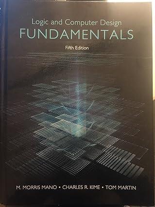
Logic And Computer Design Fundamentals
Authors: M. Morris Mano, Charles Kime, Tom Martin
5th Edition
0133760634, 978-0133760637
Students also viewed these Programming questions
Question
Answered: 1 week ago
Question
Answered: 1 week ago
Question
Answered: 1 week ago
Question
Answered: 1 week ago
Question
Answered: 1 week ago
Question
Answered: 1 week ago
Question
Answered: 1 week ago
Question
Answered: 1 week ago
Question
Answered: 1 week ago
Question
Answered: 1 week ago
Question
Answered: 1 week ago
Question
Answered: 1 week ago
Question
Answered: 1 week ago
Question
Answered: 1 week ago
Question
Answered: 1 week ago
Question
Answered: 1 week ago
Question
Answered: 1 week ago
Question
Answered: 1 week ago
Question
Answered: 1 week ago
Question
Answered: 1 week ago
Question
Answered: 1 week ago
Question
Answered: 1 week ago
View Answer in SolutionInn App


