Question
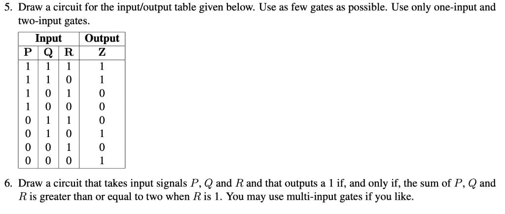
5. Draw a circuit for the input/output table given below. Use as few gates as possible. Use only one-input and two-input gates. Input PQ

5. Draw a circuit for the input/output table given below. Use as few gates as possible. Use only one-input and two-input gates. Input PQ Output R 1 1 1 1 1 1 0 1 1 0 10000 10 0 0 1 1 1 0 1 0 1 0 0 0 1 6. Draw a circuit that takes input signals P, Q and R and that outputs a 1 if, and only if, the sum of P, Q and R is greater than or equal to two when R is 1. You may use multi-input gates if you like.
Step by Step Solution
There are 3 Steps involved in it
Step: 1

Get Instant Access to Expert-Tailored Solutions
See step-by-step solutions with expert insights and AI powered tools for academic success
Step: 2

Step: 3

Ace Your Homework with AI
Get the answers you need in no time with our AI-driven, step-by-step assistance
Get StartedRecommended Textbook for
Logic And Computer Design Fundamentals
Authors: M. Morris Mano, Charles Kime, Tom Martin
5th Edition
0133760634, 978-0133760637
Students also viewed these Programming questions
Question
Answered: 1 week ago
Question
Answered: 1 week ago
Question
Answered: 1 week ago
Question
Answered: 1 week ago
Question
Answered: 1 week ago
Question
Answered: 1 week ago
Question
Answered: 1 week ago
Question
Answered: 1 week ago
Question
Answered: 1 week ago
Question
Answered: 1 week ago
Question
Answered: 1 week ago
Question
Answered: 1 week ago
Question
Answered: 1 week ago
Question
Answered: 1 week ago
Question
Answered: 1 week ago
Question
Answered: 1 week ago
Question
Answered: 1 week ago
Question
Answered: 1 week ago
Question
Answered: 1 week ago
Question
Answered: 1 week ago
Question
Answered: 1 week ago
Question
Answered: 1 week ago
View Answer in SolutionInn App


