Answered step by step
Verified Expert Solution
Question
1 Approved Answer
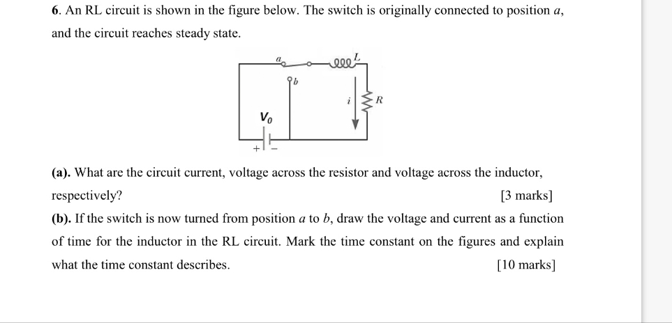
6. An RL circuit is shown in the figure below. The switch is originally connected to position a, and the circuit reaches steady state.

6. An RL circuit is shown in the figure below. The switch is originally connected to position a, and the circuit reaches steady state. Vo " eee R (a). What are the circuit current, voltage across the resistor and voltage across the inductor, respectively? [3 marks] (b). If the switch is now turned from position a to b, draw the voltage and current as a function of time for the inductor in the RL circuit. Mark the time constant on the figures and explain what the time constant describes. [10 marks]
Step by Step Solution
★★★★★
3.38 Rating (148 Votes )
There are 3 Steps involved in it
Step: 1
a In steady state when the switch is connected to position a the inductor behaves like a short circu...
Get Instant Access to Expert-Tailored Solutions
See step-by-step solutions with expert insights and AI powered tools for academic success
Step: 2

Step: 3

Document Format ( 2 attachments)
66421ddf67638_986035.pdf
180 KBs PDF File
66421ddf67638_986035.docx
120 KBs Word File
Ace Your Homework with AI
Get the answers you need in no time with our AI-driven, step-by-step assistance
Get Started


