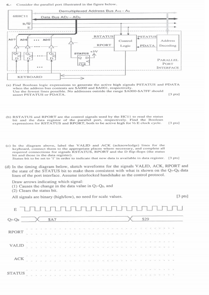
6.- Consider the parallel port illustrated in the figure below. Demultiplexed Address Bus Ais-Ao 6SHCI1 Data Bus AD-ADo R/W RSTATUS PSTATU AD7AD ..ADO Control RPORT Logic Decoding Q6 STATUS Q D PARALLEL PORT INTERFACE KEYBOARD (a) Find Boolean logic expressions to generate the active high signals PSTATUS and PDATA when the address bus contents are SA00O and SA001, respectively Use the fewest lines possible. No addresses outside the range $A000-SA7FF should assert PSTATUS or PDATA [3 pts (b) RSTATUS and RPORT are the control signals used by the HCI1 to read the status bit and the data register of the parallel port, respectively. Find the Boolcan expressions for RSTATUS and RPORT, both to be active high for E clock cycle. [3 pts) (c) In the diagram above, Iabel the VALID and ACK (acknowledge) lines for the keyboard, connect them to the appropriate places where necessary, and complete all required connections for signals RSTATUS, RPORT and the D flip-flops (he status bit and those in the data register). Status bit to be set to'1 in order to indicate that new data is available in data register. [3 pts] d) In the timing diagram below, sketch waveforms for the signals VALID, ACK, RPORT and the state of the STATUS bit to make them consistent with what is shown on the Qr-Qo data lines of the port interface. Assume interlocked handshake as the control protocol Draw arrows indicating which signal (1) Causes the change in the data value in Qr-Qo, and (2) Clears the status bit. All signals are binary (highlow), no need for scale values 13 pts] Q7-Q SA7 RPORT VALID ACK STATUS 6.- Consider the parallel port illustrated in the figure below. Demultiplexed Address Bus Ais-Ao 6SHCI1 Data Bus AD-ADo R/W RSTATUS PSTATU AD7AD ..ADO Control RPORT Logic Decoding Q6 STATUS Q D PARALLEL PORT INTERFACE KEYBOARD (a) Find Boolean logic expressions to generate the active high signals PSTATUS and PDATA when the address bus contents are SA00O and SA001, respectively Use the fewest lines possible. No addresses outside the range $A000-SA7FF should assert PSTATUS or PDATA [3 pts (b) RSTATUS and RPORT are the control signals used by the HCI1 to read the status bit and the data register of the parallel port, respectively. Find the Boolcan expressions for RSTATUS and RPORT, both to be active high for E clock cycle. [3 pts) (c) In the diagram above, Iabel the VALID and ACK (acknowledge) lines for the keyboard, connect them to the appropriate places where necessary, and complete all required connections for signals RSTATUS, RPORT and the D flip-flops (he status bit and those in the data register). Status bit to be set to'1 in order to indicate that new data is available in data register. [3 pts] d) In the timing diagram below, sketch waveforms for the signals VALID, ACK, RPORT and the state of the STATUS bit to make them consistent with what is shown on the Qr-Qo data lines of the port interface. Assume interlocked handshake as the control protocol Draw arrows indicating which signal (1) Causes the change in the data value in Qr-Qo, and (2) Clears the status bit. All signals are binary (highlow), no need for scale values 13 pts] Q7-Q SA7 RPORT VALID ACK STATUS


