

Answered step by step
Verified Expert Solution
Question
1 Approved Answer
6. Implementation Describe the implementation of the circuit. Provide specifications - IC models, number of components inside ICs, quantity of ICs used, etc. Give photograph
6. Implementation
Describe the implementation of the circuit. Provide specifications - IC models, number of components inside ICs, quantity of ICs used, etc. Give photograph of hardware?
note: project name-Project on Seven Segment Display.
please answer the question 6 with the help of given pictures and project name.
please see clearly the picture 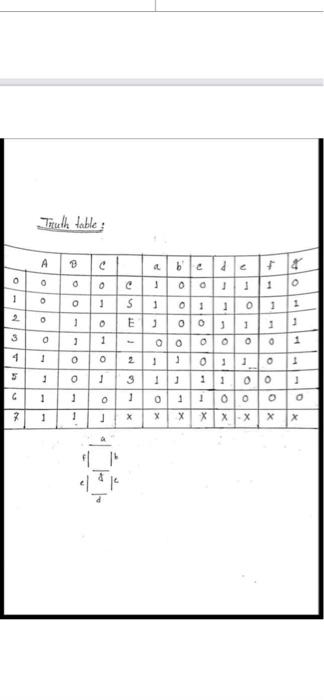
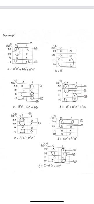
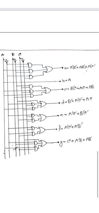
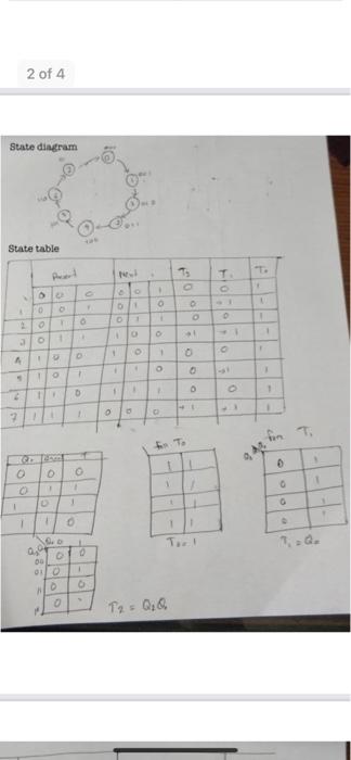
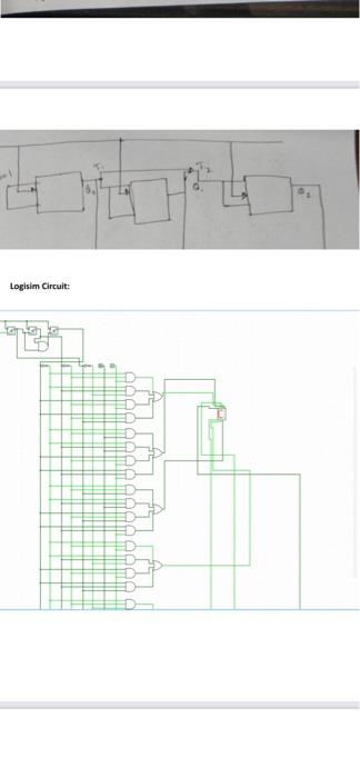
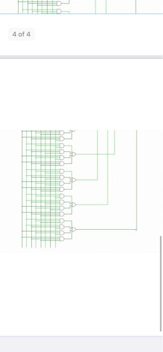
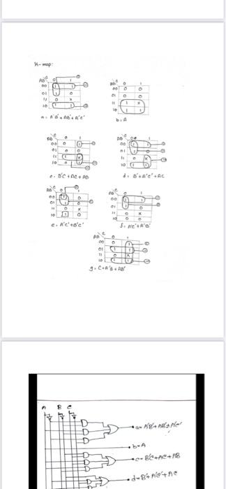
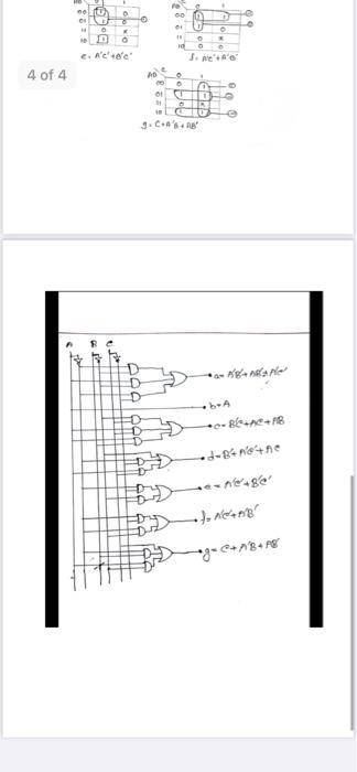
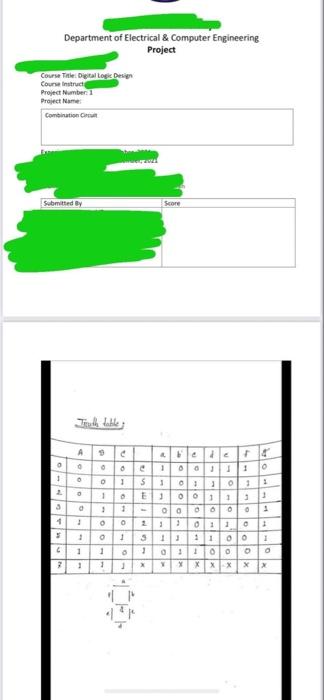
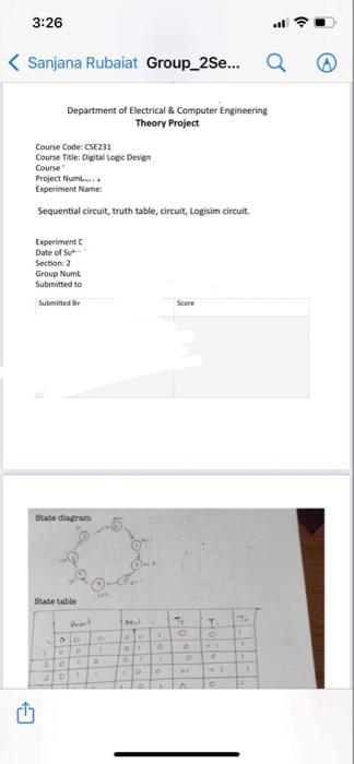
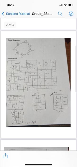
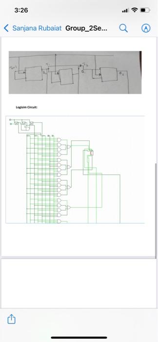
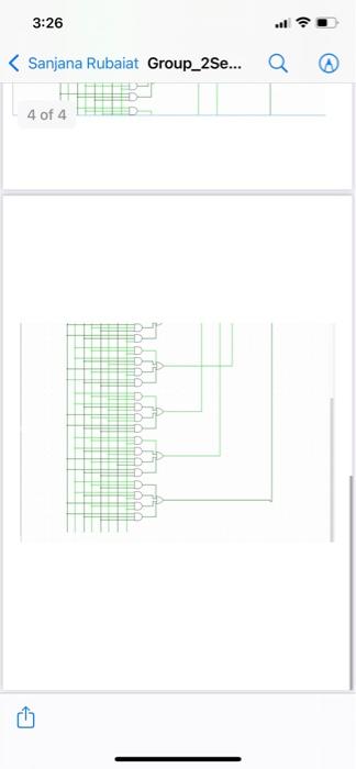
map 5829 J. b. 66 ca 0 00 TO 100 2. BCAA die'.AC be ON . O Non c. A'ec 5. Ne'' AD 9. C.Ang sa nesret .be .-8.18 .d-B4netne coltd 6 co 0 . E.Refer 3.ne.de 4084 AD 10 . DO DI ching He Q * R18 B) "name Department of Electrical & Computer Engineering Project Course Title: Digital Logic Design Course in Project Number 1 Project Name Combination Submitted by Score Teadh habile 9 d A . be 100 lo 1 2 o . 1 WMO lo--- + GOOOOO . 1 1 11:1000 1 YX X X X X 3:26 Sanjana Rubaiat Group_2Se... Q Department of Electrical & Computer Engineering Theory Project Course Code: CSE231 Course Title: Digital Logic Design Course Project Num Experiment Name: Sequential circuit, truth table, circuit, Logisim circuit. Experiment ate of Sut Section 2 Group Numt Submitted to Submitted Score state din State table 1 O D D 30 3:26 Sanjana Rubaiat Group_2Se... 2 of 4 State diagram Suate table " FO 1 D 0 Oo 1 + 2 AR . o 1 To D To QQ 3:26 . Sanjana Rubaiat Group_2Se... a Logisim Circuit 3:26 . Sanjana Rubaiat Group_2Se... 4 of 4 Titulla table B ble PP + + ? r 3 1 o 0 1 11 o 1 1 1 1 --OOOO OOOO O 1 0 0 1 -- 1 1 o 00 3 1 0 o 0 X 1 X 1 X 0 0 XX 7 1 1 X X x X 11 el - op 0 1 AS 00 AD 00 OB 0 o 01 1 o X 1 10 o 0 11 o 1 1 10 lo an6.AB'+ Act b. A AB 00 o 0 11 00 10 a 1 O O AD 00 . bor x L 10 0 B'C + AC + AB co d. G'A'e' AC AB 0 1 00 OI AB 00 0 0 x o e a I! 0 0 10 01 O 11 X 10 O O $. AC' A'C 00 e. A'c' 6'c' oc e AD 00 11 lo X 9. C+A's + AB A - Ag+ Agrler D D D 000000 b-A -86+A+18 d-B+ n'tne mene+86 / ACHAR *9*+A8+ Ag C 2 of 4 State diagram State table P T FO . D -O o 0 OO. 1 0 2 - O 3 1 . + 0 1 A 1 0 1 1 D O 2 2 fon FT 0 0 1 1 2 1 1 1 1 0. 0, T. Q. O T2 = QQ Logisim Circuit: 4 of 4 map 5829 J. b. 66 ca 0 00 TO 100 2. BCAA die'.AC be ON . O Non c. A'ec 5. Ne'' AD 9. C.Ang sa nesret .be .-8.18 .d-B4netne coltd 6 co 0 . E.Refer 3.ne.de 4084 AD 10 . DO DI ching He Q * R18 B) "name Department of Electrical & Computer Engineering Project Course Title: Digital Logic Design Course in Project Number 1 Project Name Combination Submitted by Score Teadh habile 9 d A . be 100 lo 1 2 o . 1 WMO lo--- + GOOOOO . 1 1 11:1000 1 YX X X X X 3:26 Sanjana Rubaiat Group_2Se... Q Department of Electrical & Computer Engineering Theory Project Course Code: CSE231 Course Title: Digital Logic Design Course Project Num Experiment Name: Sequential circuit, truth table, circuit, Logisim circuit. Experiment ate of Sut Section 2 Group Numt Submitted to Submitted Score state din State table 1 O D D 30 3:26 Sanjana Rubaiat Group_2Se... 2 of 4 State diagram Suate table " FO 1 D 0 Oo 1 + 2 AR . o 1 To D To QQ 3:26 . Sanjana Rubaiat Group_2Se... a Logisim Circuit 3:26 . Sanjana Rubaiat Group_2Se... 4 of 4 Titulla table B ble PP + + ? r 3 1 o 0 1 11 o 1 1 1 1 --OOOO OOOO O 1 0 0 1 -- 1 1 o 00 3 1 0 o 0 X 1 X 1 X 0 0 XX 7 1 1 X X x X 11 el - op 0 1 AS 00 AD 00 OB 0 o 01 1 o X 1 10 o 0 11 o 1 1 10 lo an6.AB'+ Act b. A AB 00 o 0 11 00 10 a 1 O O AD 00 . bor x L 10 0 B'C + AC + AB co d. G'A'e' AC AB 0 1 00 OI AB 00 0 0 x o e a I! 0 0 10 01 O 11 X 10 O O $. AC' A'C 00 e. A'c' 6'c' oc e AD 00 11 lo X 9. C+A's + AB A - Ag+ Agrler D D D 000000 b-A -86+A+18 d-B+ n'tne mene+86 / ACHAR *9*+A8+ Ag C 2 of 4 State diagram State table P T FO . D -O o 0 OO. 1 0 2 - O 3 1 . + 0 1 A 1 0 1 1 D O 2 2 fon FT 0 0 1 1 2 1 1 1 1 0. 0, T. Q. O T2 = QQ Logisim Circuit: 4 of 4 Step by Step Solution
There are 3 Steps involved in it
Step: 1

Get Instant Access to Expert-Tailored Solutions
See step-by-step solutions with expert insights and AI powered tools for academic success
Step: 2

Step: 3
Ace Your Homework with AI
Get the answers you need in no time with our AI-driven, step-by-step assistance
Get Started
Building Database Driven Catalogs
Authors: Sherif Danish
1st Edition
0070153078, 978-0070153073