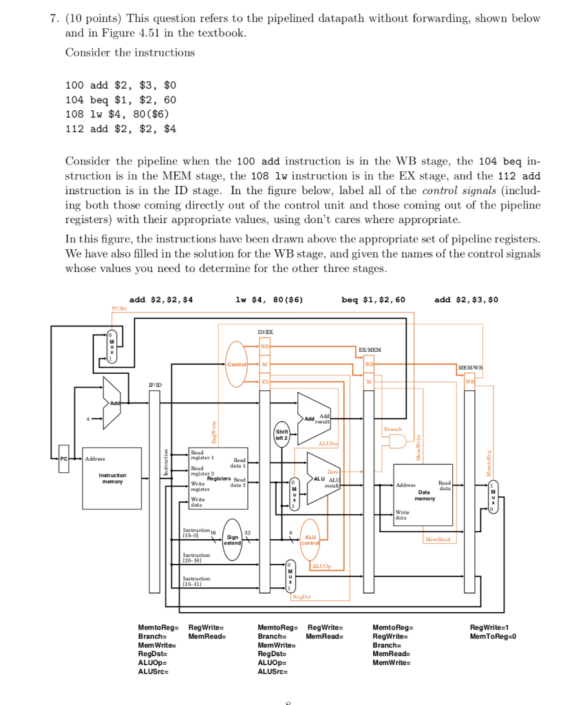
7. (10 points) This question refers to the pipelined datapath without forwarding, shown below and in Figure 4.51 in the textbook Consider the instructions 100 add $2, $3, $0 104 beq $1, $2, 60 108 lw $4, 80 ($6) 112 add $2, $2, $4 Consider the pipeline when the 100 add instruction is in the WB stage, the 104 beq in- struction is in the MEM stage, the 108 lw instruction is in the EX stage, and the 112 add instruction is in the ID stage. In the figure below, label all of the control signals (includ- ing both those coming directly out of the control unit and those coming out of the pipeline registers) with their appropriate values, using don't cares where appropriate In this figure, the instructions have been drawn above the appropriate set of pipeline registers. We have also filled in the solution for the WB stage, and given the names of the control signals whose values you need to determine for the other three stages add $2, $2, $4 lw $4, 80 ($6) beq $1, $2, 60 add $2, $3, $0 PCSr ID EX EXMEM MEM FID Add Add Shift left 2 PC register 1 data 1 register 2 Registers Read data 2 ALU ALU result Write Data data Write Write Instruction16 15-0 Sign ALU Mem Read ALU 15-11 MemtoReg-RegWrite- Branch- Mem Write- MemtoReg RegWrite- Branch MemRead- MemWrite- RegDst- ALUOpz ALUSrc MemtoReg- RegWrite- Branch- RegWrite-1 MemToReg-0 MemRead- ALUOp- ALUSrc MemWrite- 7. (10 points) This question refers to the pipelined datapath without forwarding, shown below and in Figure 4.51 in the textbook Consider the instructions 100 add $2, $3, $0 104 beq $1, $2, 60 108 lw $4, 80 ($6) 112 add $2, $2, $4 Consider the pipeline when the 100 add instruction is in the WB stage, the 104 beq in- struction is in the MEM stage, the 108 lw instruction is in the EX stage, and the 112 add instruction is in the ID stage. In the figure below, label all of the control signals (includ- ing both those coming directly out of the control unit and those coming out of the pipeline registers) with their appropriate values, using don't cares where appropriate In this figure, the instructions have been drawn above the appropriate set of pipeline registers. We have also filled in the solution for the WB stage, and given the names of the control signals whose values you need to determine for the other three stages add $2, $2, $4 lw $4, 80 ($6) beq $1, $2, 60 add $2, $3, $0 PCSr ID EX EXMEM MEM FID Add Add Shift left 2 PC register 1 data 1 register 2 Registers Read data 2 ALU ALU result Write Data data Write Write Instruction16 15-0 Sign ALU Mem Read ALU 15-11 MemtoReg-RegWrite- Branch- Mem Write- MemtoReg RegWrite- Branch MemRead- MemWrite- RegDst- ALUOpz ALUSrc MemtoReg- RegWrite- Branch- RegWrite-1 MemToReg-0 MemRead- ALUOp- ALUSrc MemWrite


