Question: 7,2o please Mechanics_of_Materials_7th_edit x OFile C:/Users/aser/Downloads/Mechanics_of_Materials_7th_edition_beer.pdf ... 506 of 897 V Draw O Erase 15 *15 Fig. P7.17 Fig. P7.18 7.19 Two wooden members of
7,2o please
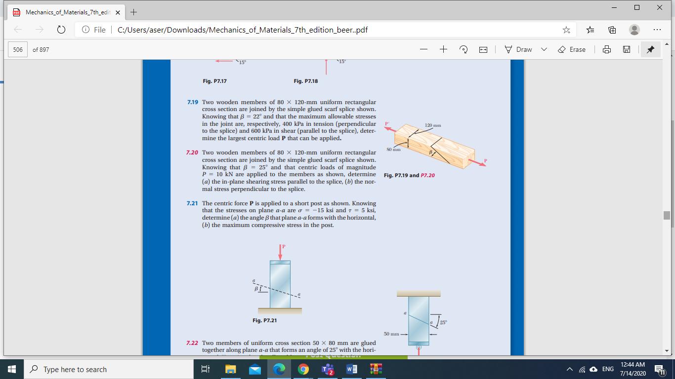
Mechanics_of_Materials_7th_edit x OFile C:/Users/aser/Downloads/Mechanics_of_Materials_7th_edition_beer.pdf ... 506 of 897 V Draw O Erase 15 *15" Fig. P7.17 Fig. P7.18 7.19 Two wooden members of 80 X 120-mm uniform rectangular cross section are joined by the simple glued scarf splice shown. Knowing that B = 22 and that the maximum allowable stresses in the joint are, respectively, 400 kPa in tension (perpendicular to the splice) and 600 kPa in shear (parallel to the splice), deter- mine the largest centric load P that can be applied. 120 mm 7.20 Two wooden members of 80 X 120-mm uniform rectangular cross section are joined by the simple glued scarf splice shown. Knowing thatB = 25 and that centric loads of magnitude P = 10 kN are applied to the members as shown, determine (a) the in-plane shearing stress parallel to the splice, (b) the nor- mal stress perpendicular to the splice. Fig. P7.19 and P7.20 7.21 The centric force P is applied to a short post as shown. Knowing that the stresses on plane a-a are o = -15 ksi andT = 5 ksi, determine (a) the angle B that plane a-a forms with the horizontal, (b) the maximum compressive stress in the pot. Fig. P7.21 50 mm 7.22 Two members of uniform cross section 50 x 80 mm are glued together along plane a-a that forms an angle of 25 with the hori- 12:44 AM P Type here to search ENG 7/14/2020
Step by Step Solution
3.53 Rating (153 Votes )
There are 3 Steps involved in it
An... View full answer

Get step-by-step solutions from verified subject matter experts


