Answered step by step
Verified Expert Solution
Link Copied!

Question

1 Approved Answer

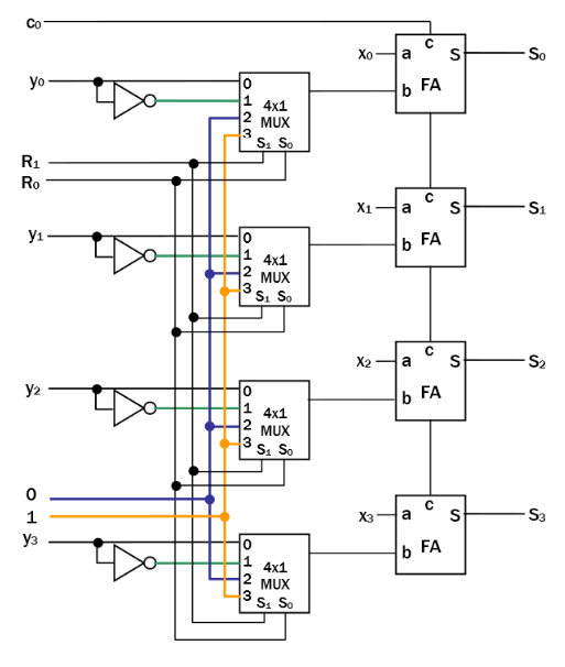
(8 pts) Using the module definitions from Problem 1 (4-bit ripple carry adder) and Problem 6 (Figure 3-33), implement the arithmetic circuit shown in the
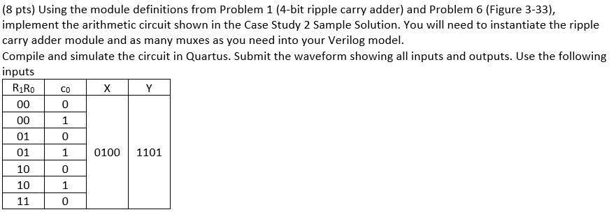
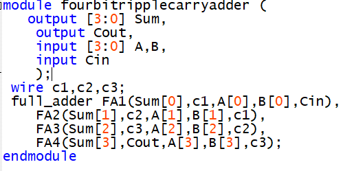
image text in transcribedimage text in transcribedimage text in transcribedimage text in transcribed

(8 pts) Using the module definitions from Problem 1 (4-bit ripple carry adder) and Problem 6 (Figure 3-33), implement the arithmetic circuit shown in the Case Study 2 Sample Solution. You will need to instantiate the ripple carry adder module and as many muxes as you need into your Verilog model. Compile and simulate the circuit in Quartus. Submit the waveform showing all inputs and outputs. Use the following inputs R1Ro Co 0 00 01 01 10 10 ? 0 1 0 1 0 0100 1101 (8 pts) Using the module definitions from Problem 1 (4-bit ripple carry adder) and Problem 6 (Figure 3-33), implement the arithmetic circuit shown in the Case Study 2 Sample Solution. You will need to instantiate the ripple carry adder module and as many muxes as you need into your Verilog model. Compile and simulate the circuit in Quartus. Submit the waveform showing all inputs and outputs. Use the following inputs R1Ro Co 0 00 01 01 10 10 ? 0 1 0 1 0 0100 1101
Step by Step Solution

There are 3 Steps involved in it

Step: 1

blur-text-image

Get Instant Access to Expert-Tailored Solutions

See step-by-step solutions with expert insights and AI powered tools for academic success

Step: 2

blur-text-image

Step: 3

blur-text-image

Ace Your Homework with AI

Get the answers you need in no time with our AI-driven, step-by-step assistance

Get Started

Recommended Textbook for

Database Systems Introduction To Databases And Data Warehouses

Authors: Nenad Jukic, Susan Vrbsky, Svetlozar Nestorov

1st Edition

1943153191, 978-1943153190

More Books

Students also viewed these Databases questions