Answered step by step
Verified Expert Solution
Question
1 Approved Answer
8- The block diagram shown in the following figure represents the hardware that implements the following microoperations (ba'+b+c)(a+b+c).: R1+R2 (a b'ctab'ch: RI-R1+R2 Where R1 and
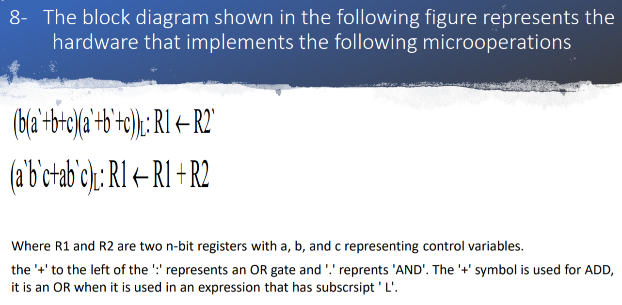
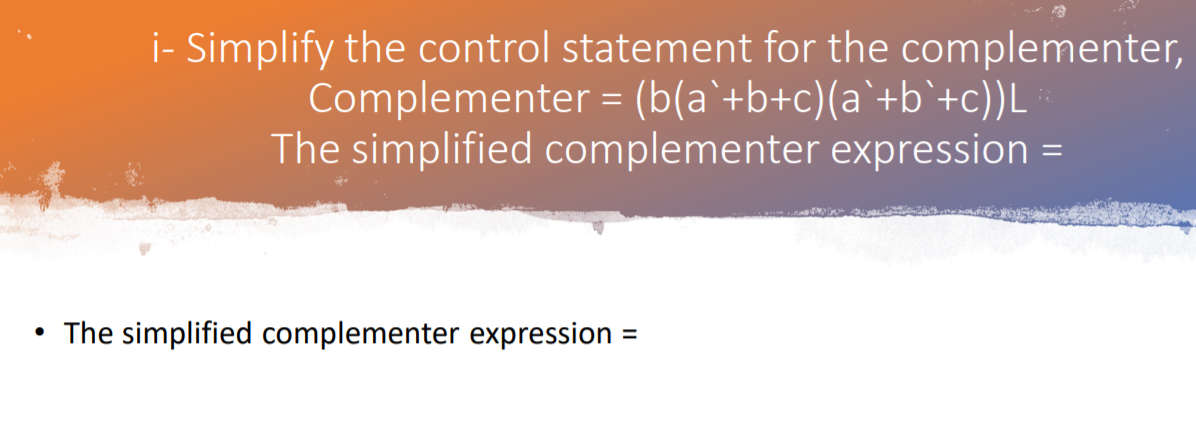
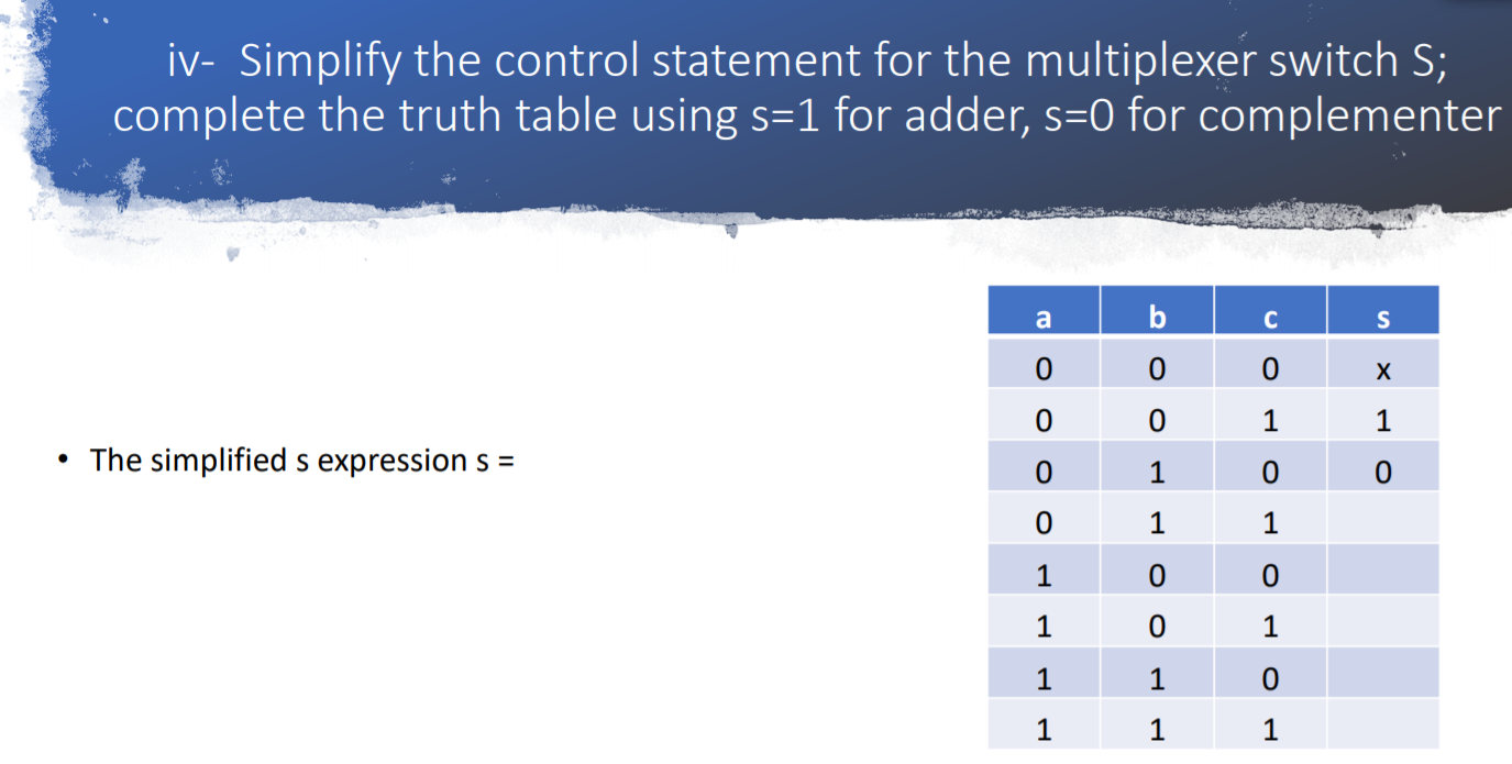
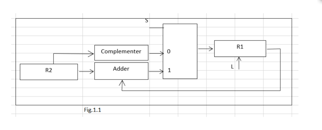
8- The block diagram shown in the following figure represents the hardware that implements the following microoperations (ba'+b+c)(a+b+c).: R1+R2 (a b'ctab'ch: RI-R1+R2 Where R1 and R2 are two n-bit registers with a, b, and c representing control variables. the '+' to the left of the ':' represents an OR gate and '.' reprents 'AND'. The '+' symbol is used for ADD, it is an OR when it is used in an expression that has subscrsipt 'L'. R1 Complementer 0 R2 Adder L 1 1 Fig. 1.1 i- Simplify the control statement for the complementer, Complementer = (b(a'+b+c)(a +b+c))L The simplified complementer expression = . The simplified complementer expression ji- Simplify the control statement for the adder; Adder=(a bc+abc)L. The simplified adder expression = iii- Simplify the control statement for the load input of R1; L=(b(a'+b+c)(a +b +c))L+(a`bc+abc)L. The simplified load expression for L= iv- Simplify the control statement for the multiplexer switch S; complete the truth table using s=1 for adder, s=0 for complementer a b S 0 x 0 0 1 1 The simplified s expression s = 0 1 0 0 1 1 1 0 0 1 0 1 1 1 0 1 1 1
Step by Step Solution
There are 3 Steps involved in it
Step: 1
Get Instant Access to Expert-Tailored Solutions
See step-by-step solutions with expert insights and AI powered tools for academic success
Step: 2
Step: 3
Ace Your Homework with AI
Get the answers you need in no time with our AI-driven, step-by-step assistance
Get Started