

Answered step by step
Verified Expert Solution
Question
1 Approved Answer
8-121 In large steam power plants, the feedwater is frequently heated in closed feedwater heaters, which are basically heat exchangers, by steam extracted from
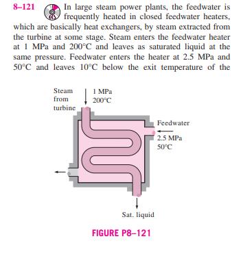
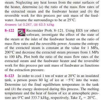
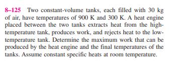
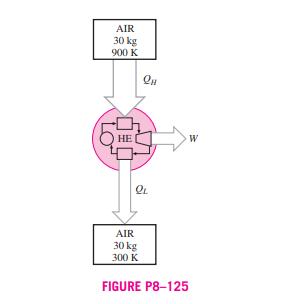
8-121 In large steam power plants, the feedwater is frequently heated in closed feedwater heaters, which are basically heat exchangers, by steam extracted from the turbine at some stage. Steam enters the feedwater heater at 1 MPa and 200C and leaves as saturated liquid at the same pressure. Feedwater enters the heater at 2.5 MPa and 50C and leaves 10C below the exit temperature of the Steam from 1 MPa 200C turbine Sat. liquid FIGURE P8-121 Feedwater 2.5 MPa 50C steam. Neglecting any heat losses from the outer surfaces of the heater, determine (a) the ratio of the mass flow rates of the extracted steam and the feedwater heater and (b) the reversible work for this process per unit mass of the feed- water. Assume the surroundings to be at 25C. Answers: (a) 0.247, (b) 63.5 kJ/kg 8-122 Reconsider Prob. 8-121. Using EES (or other) software, investigate the effect of the state of the steam at the inlet of the feedwater heater on the ratio of mass flow rates and the reversible power. Assume the entropy of the extracted steam is constant at the value for 1 MPa, 200C and decrease the extracted steam pressure from 1 MPa to 100 kPa. Plot both the ratio of the mass flow rates of the extracted steam and the feedwater heater and the reversible work for this process per unit mass of feedwater as functions of the extraction pressure. 8-123 In order to cool 1 ton of water at 20C in an insulated tank, a person pours 80 kg of ice at -5C into the water. Determine (a) the final equilibrium temperature in the tank and (b) the exergy destroyed during this process. The melting temperature and the heat of fusion of ice at atmospheric pres- sure are 0C and 333.7 kJ/kg, respectively. Take T = 20C. 8-124 Consider a 12-L evacuated rigid bottle that is sur- rounded by the atmosphere at 100 kPa and 17C. A valve at the neck of the bottle is now opened and the atmospheric air is allowed to flow into the bottle. The air trapped in the bottle eventually reaches thermal equilibrium with the atmosphere as a result of heat transfer through the wall of the bottle. The valve remains open during the process so that the trapped air also reaches mechanical equilibrium with the atmosphere. Determine the net heat transfer through the wall of the bottle and the exergy destroyed during this filling process. 12 L Evacuated 100 kPa 17C FIGURE P8-124 8-125 Two constant-volume tanks, each filled with 30 kg of air, have temperatures of 900 K and 300 K. A heat engine placed between the two tanks extracts heat from the high- temperature tank, produces work, and rejects heat to the low- temperature tank. Determine the maximum work that can be produced by the heat engine and the final temperatures of the tanks. Assume constant specific heats at room temperature. AIR 30 kg 900 K LO K AIR 30 kg 300 K QL FIGURE P8-125 W 8-121 In large steam power plants, the feedwater is frequently heated in closed feedwater heaters, which are basically heat exchangers, by steam extracted from the turbine at some stage. Steam enters the feedwater heater at 1 MPa and 200C and leaves as saturated liquid at the same pressure. Feedwater enters the heater at 2.5 MPa and 50C and leaves 10C below the exit temperature of the Steam from 1 MPa 200C turbine Sat. liquid FIGURE P8-121 Feedwater 2.5 MPa 50C steam. Neglecting any heat losses from the outer surfaces of the heater, determine (a) the ratio of the mass flow rates of the extracted steam and the feedwater heater and (b) the reversible work for this process per unit mass of the feed- water. Assume the surroundings to be at 25C. Answers: (a) 0.247, (b) 63.5 kJ/kg 8-122 Reconsider Prob. 8-121. Using EES (or other) software, investigate the effect of the state of the steam at the inlet of the feedwater heater on the ratio of mass flow rates and the reversible power. Assume the entropy of the extracted steam is constant at the value for 1 MPa, 200C and decrease the extracted steam pressure from 1 MPa to 100 kPa. Plot both the ratio of the mass flow rates of the extracted steam and the feedwater heater and the reversible work for this process per unit mass of feedwater as functions of the extraction pressure. 8-123 In order to cool 1 ton of water at 20C in an insulated tank, a person pours 80 kg of ice at -5C into the water. Determine (a) the final equilibrium temperature in the tank and (b) the exergy destroyed during this process. The melting temperature and the heat of fusion of ice at atmospheric pres- sure are 0C and 333.7 kJ/kg, respectively. Take T = 20C. 8-124 Consider a 12-L evacuated rigid bottle that is sur- rounded by the atmosphere at 100 kPa and 17C. A valve at the neck of the bottle is now opened and the atmospheric air is allowed to flow into the bottle. The air trapped in the bottle eventually reaches thermal equilibrium with the atmosphere as a result of heat transfer through the wall of the bottle. The valve remains open during the process so that the trapped air also reaches mechanical equilibrium with the atmosphere. Determine the net heat transfer through the wall of the bottle and the exergy destroyed during this filling process. 12 L Evacuated 100 kPa 17C FIGURE P8-124 8-125 Two constant-volume tanks, each filled with 30 kg of air, have temperatures of 900 K and 300 K. A heat engine placed between the two tanks extracts heat from the high- temperature tank, produces work, and rejects heat to the low- temperature tank. Determine the maximum work that can be produced by the heat engine and the final temperatures of the tanks. Assume constant specific heats at room temperature. AIR 30 kg 900 K LO K AIR 30 kg 300 K QL FIGURE P8-125 W
Step by Step Solution
There are 3 Steps involved in it
Step: 1

Get Instant Access to Expert-Tailored Solutions
See step-by-step solutions with expert insights and AI powered tools for academic success
Step: 2

Step: 3
Ace Your Homework with AI
Get the answers you need in no time with our AI-driven, step-by-step assistance
Get Started
Fundamentals Of Hydraulic Engineering Systems
Authors: Robert J. Houghtalen, A. Osman H. Akan, Ned H. C. Hwang
4th Edition