

Answered step by step
Verified Expert Solution
Question
1 Approved Answer
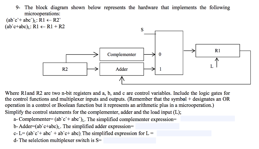
9- The block diagram shown below represents the hardware that implements the following microoperations (abc'+ abc'): R1 R2. (abc+abc): R1 R1+ R2 R1 Complementer 0
Step by Step Solution
There are 3 Steps involved in it
Step: 1

Get Instant Access to Expert-Tailored Solutions
See step-by-step solutions with expert insights and AI powered tools for academic success
Step: 2

Step: 3
Ace Your Homework with AI
Get the answers you need in no time with our AI-driven, step-by-step assistance
Get Started
Database Security
Authors: Alfred Basta, Melissa Zgola
1st Edition
1435453905, 978-1435453906